Photodiode array, method of manufacturing the same, and detecting device
a photodiode array and manufacturing method technology, applied in the direction of solid-state devices, semiconductor devices, radio-controlled devices, etc., can solve the problem of high lattice defect density in the edge portion of the epitaxial multilayer that cannot be derived, and achieve the effect of improving the manufacturing efficiency increasing the reliability of the photodiode array
- Summary
- Abstract
- Description
- Claims
- Application Information
AI Technical Summary
Benefits of technology
Problems solved by technology
Method used
Image
Examples
first embodiment
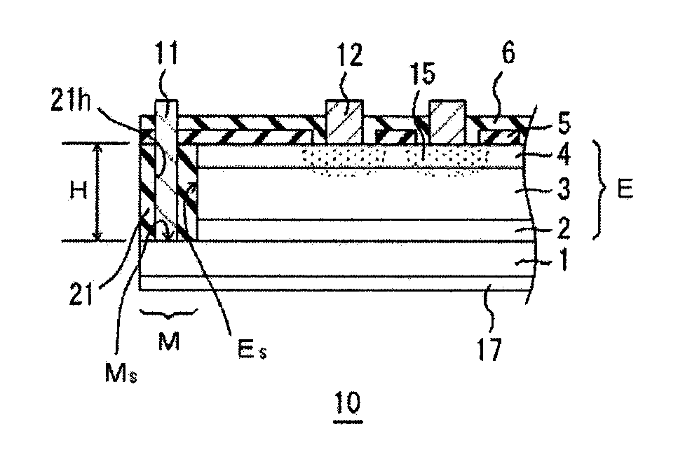
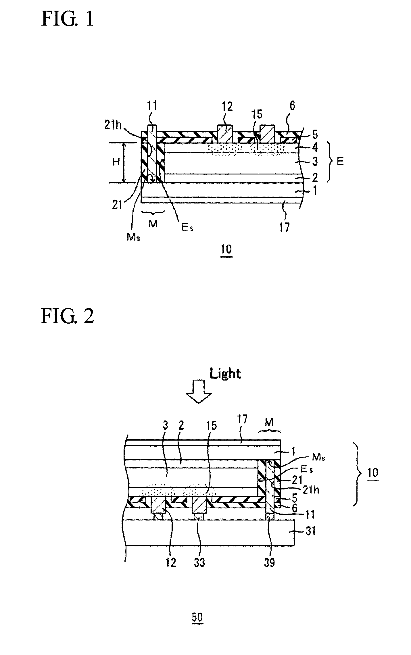
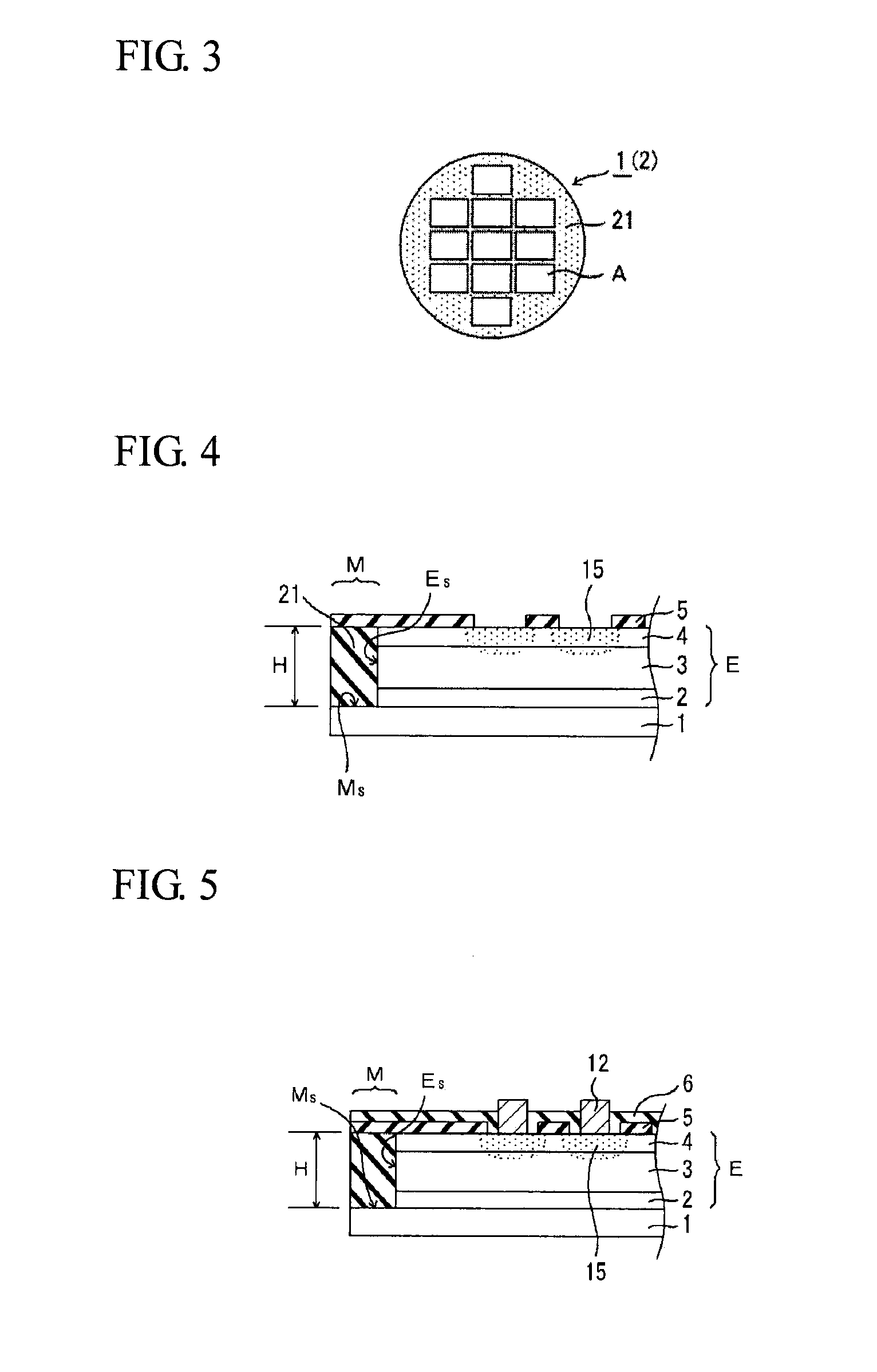
[0040]FIG. 1 is a cross-sectional view of an edge portion of a photodiode array 10 according to a first embodiment of the present invention. An epitaxial multilayer E including an InP buffer layer 2, an absorption layer 3, and an InP window layer 4 is disposed on an n+-type InP substrate 1 doped with sulfur (S). The absorption layer 3 may be composed of any Group III-V compound semiconductor. For example, In0.53Ga0.47As may be used as the absorption layer 3. In the case of In0.53Ga0.47As, the photodiode array 10 has responsivity at a wavelength of 1.7 μm or less in the near infrared. Each photodiode includes a p-type region 15 formed by selectively diffusing zinc (Zn) through an opening of a mask pattern 5 for selective diffusion. In each photodiode, a p-n junction or a p-i-n junction is formed at an end of the p-type region 15.
[0041]A p-side electrode 12, which is a first conductive-side electrode, is provided for each photodiode in order to read photogenerated charges generated by...
second embodiment
[0059]FIG. 7 is a view showing a photodiode array 10 according to a second embodiment of the present invention. Referring to FIG. 7, an insulating film 21e is disposed between a common n-side electrode 11 and an epitaxial multilayer E. Also in this embodiment, a non-growth part M where the common n-side electrode 11 is to be formed is ensured by a selective growth mask 21. That is, etching of an edge portion of the epitaxial multilayer E for the purpose of formation of the n-side electrode 11 is not performed. Accordingly, in FIG. 7, a surface Ms of the non-growth part M of an InP substrate 1 is a non-processed flat surface continuous from the inside of the InP substrate 1. In addition, a wall surface Es of the edge of the epitaxial multilayer E is a smooth, flat surface. Except for the structures of the n-side electrode 11, the insulating film 21e etc. disposed near the non-growth part M, other structures are the same as those of the photodiode array 10 shown in FIG. 1.
[0060]In man...
third embodiment
[0066]FIG. 8 is a view showing a photodiode array 10 according to a third embodiment of the present invention. Referring to FIG. 8, a protective film 6 and a selective diffusion mask 5 are disposed between an n-side electrode 11 and an epitaxial multilayer E. Also in this embodiment, a non-growth part M where the common n-side electrode 11 is to be formed is ensured by a selective growth mask 21. That is, etching of an edge portion of the epitaxial multilayer E for the purpose of formation of the n-side electrode 11 is not performed. Accordingly, in FIG. 8, a surface Ms of the non-growth part M of an InP substrate 1 is a non-processed flat surface continuous from the inside of the InP substrate 1. In addition, a wall surface Es of the edge of the epitaxial multilayer E is a smooth, flat surface. Except for the structures of part of the n-side electrode 11, the protective film 6, and the selective diffusion mask 5, the part being located near the non-growth part M, other structures a...
PUM
 Abstract
Description
Claims
Application Information
 - R&D
- Intellectual Property
- Life Sciences
- Materials
- Tech Scout
- Unparalleled Data Quality
- Higher Quality Content
- 60% Fewer Hallucinations
Browse by: Latest US Patents, China's latest patents, Technical Efficacy Thesaurus, Application Domain, Technology Topic, Popular Technical Reports.
© 2025 PatSnap. All rights reserved.Legal|Privacy policy|Modern Slavery Act Transparency Statement|Sitemap|About US| Contact US: help@patsnap.com


