

Force fluid flow energy harvester
- Summary
- Abstract
- Description
- Claims
- Application Information
AI Technical Summary
Benefits of technology
Problems solved by technology
Method used
Image

Examples
Embodiment Construction
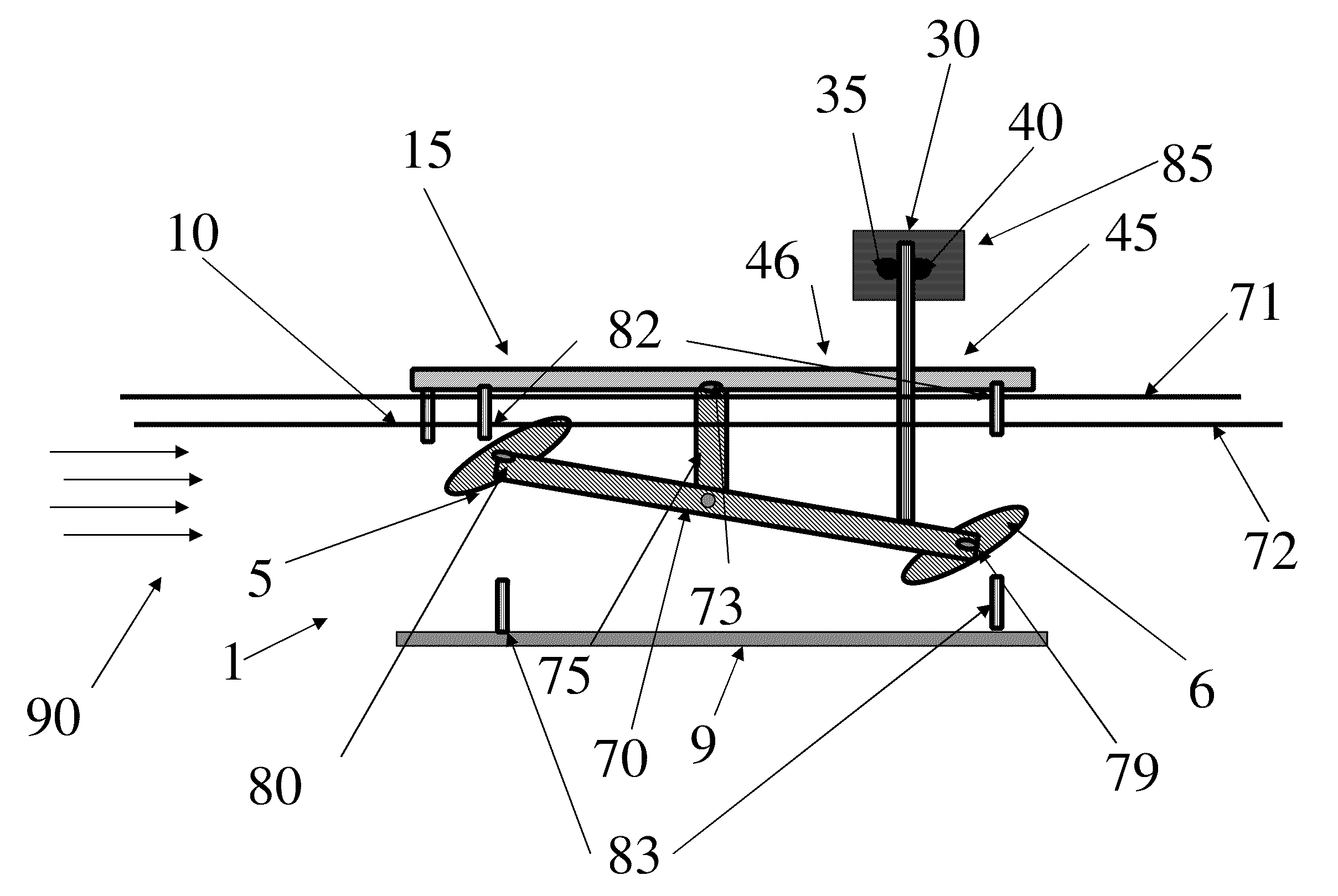
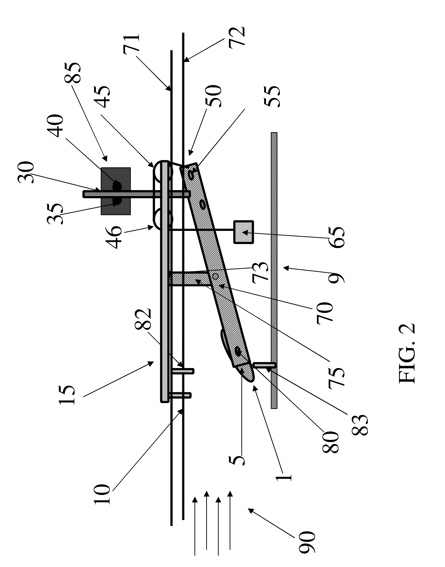
[0050]A reaction energy harvester 1 for use in hydraulic flows according to the present invention is shown in FIGS. 2, 3, and 4. The energy harvester comprises inflow fluid channel walls 4 (shown on FIG. 4), energy harvester channel side walls 8 that receive a flow 90 from the inflow channel walls 4, outflow fluid channel walls 6 that direct the flow from the channel side walls, and a foil / wing 5 mounted so it may rotate between the channel side walls. A stall baffle 10 is located downstream of the inflow fluid channel walls 4. The reaction energy harvester 1 also comprises top and bottom chamber walls and extend along the length of the foil / wing, like top and bottom walls that would be parallel to each other and perpendicular to the channel side walls 8 that can also be curved either in the side or top and bottom walls in this configuration and having opposite elevations in the plane parallel to a fluid flow path defined by the flow 90 through a channel formed at least in part by t...
PUM
 Abstract
Description
Claims
Application Information