
R-t-b sintered magnet and method for producing the same

a sintered magnet and r-t-b technology, applied in the field of r-t-b based sintered magnets, can solve the problems of reducing productivity, not meeting the demands of reducing the size of motors or improving performance, and the magnets are more easily cracked from their junctions, so as to achieve high coercivity and high remanen

Active Publication Date: 2010-02-25
HITACHI METALS LTD
View PDF6 Cites 9 Cited by
  • Summary
  • Abstract
  • Description
  • Claims
  • Application Information

AI Technical Summary

Benefits of technology

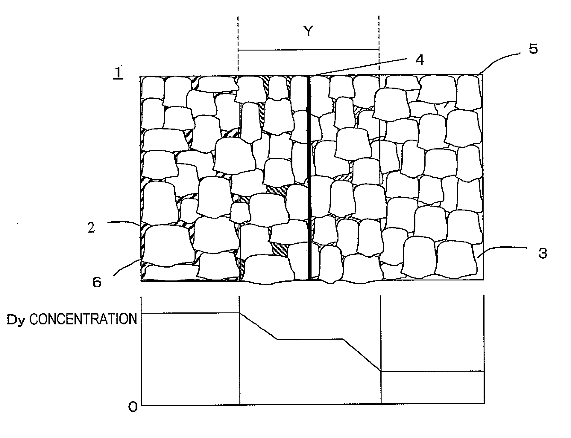
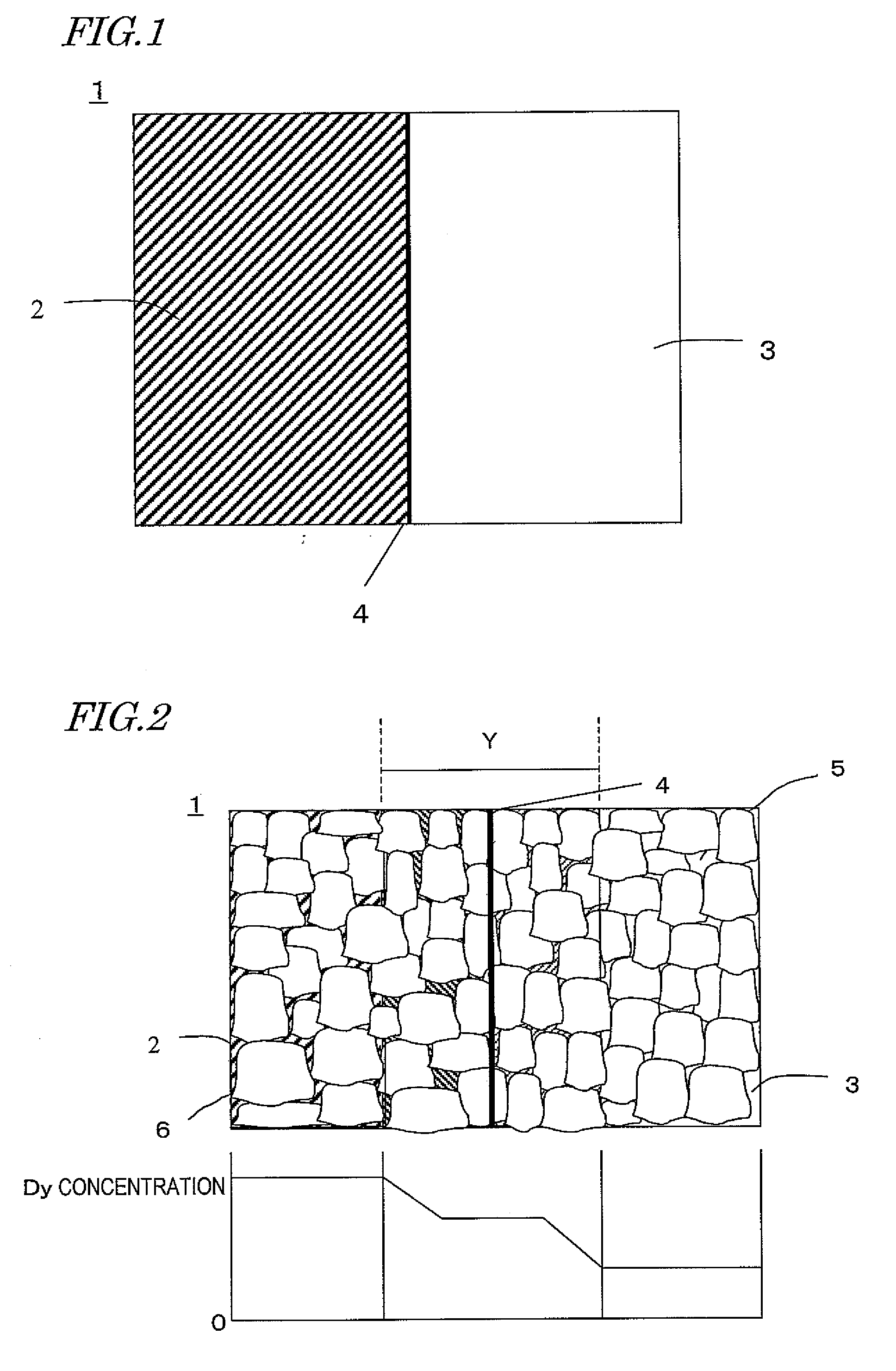
[0031]According to various preferred embodiments of the present invention, a region with high remanence Br and a region with high coercivity HcJ are formed as integral portions of a magnet by a sintering process, and a heavy rare-earth element RH is diffused in the junction between those two regions. As a result, the two regions can be combined together firmly without using any adhesive.
[0032]In addition, by changing some process parameters such as a green density according to a difference in the concentration of the heavy rare-earth element RH between the compact portions to be combined together, the deformation, which would otherwise be caused due to a difference in thermal shrinkage rate during the sintering process of a magnet if the heavy rare-earth element RH had varying concentrations, can be minimized.

Problems solved by technology

If such a combined magnet needs to be made, however, it takes extra time to complete that bonding process, thus causing a decrease in productivity.
However, the techniques disclosed in both of these documents are supposed to be used to make ferrite magnets, and will not meet the demands for reducing the size of motors or improving the performance thereof.
And the higher the temperature at which such a magnet is used, the more easily the magnet will crack from their junction due to a difference in sintering shrinkage rate between those materials.

Method used


Image

  • R-t-b sintered magnet and method for producing the same
  • R-t-b sintered magnet and method for producing the same
  • R-t-b sintered magnet and method for producing the same

Examples


example 1

[0076]First, an ingot of Material Alloy #1 that had been prepared so as to have a composition including 26.0 mass % of Nd, 5.0 mass % of Pr, less than mass % of Dy, 1.00 mass % of B, 0.90 mass % of Co, 0.1 mass % of Cu, 0.20 mass % of Al, and Fe as the balance was melted, quenched and solidified by strip casting method as described above, thereby making thin alloy flakes with thicknesses of 0.2 mm to 0.3 mm.

[0077]In the meantime, an ingot of Material Alloy #2 that had been prepared so as to have a composition including 16.5 mass % of Nd, 5.0 mass % of Pr, 10.00 mass % of Dy, 1.00 mass % of B, 0.90 mass % of Co, 0.1 mass % of Cu, mass % of Al, and Fe as the balance was also melted, quenched and solidified by strip casting method as described above, thereby making thin alloy flakes with thicknesses of 0.2 mm to 0.3 mm.

[0078]Next, two containers were loaded with these two types of thin alloy flakes and then introduced into a furnace for hydrogen absorption, which was filled with a hydr...

example 2

[0082]First, an ingot of Material Alloy #1 that had been prepared so as to have a composition including 26.0 mass % of Nd, 5.0 mass % of Pr, less than 0.05 mass % of Dy, 1.00 mass % of B, 0.90 mass % of Co, 0.1 mass % of Cu, 0.20 mass % of Al, and Fe as the balance was melted with a strip caster and then quenched and solidified, thereby making thin alloy flakes with thicknesses of 0.2 mm to 0.3 mm.

[0083]In the meantime, an ingot of Material Alloy #2 that had been prepared so as to have a composition including 16.5 mass % of Nd, 5.0 mass % of Pr, 10.00 mass % of Dy, 1.00 mass % of B, 0.90 mass % of Co, 0.1 mass % of Cu, 0.20 mass % of Al, and Fe as the balance was also melted with a strip caster and then quenched and solidified, thereby making thin alloy flakes with thicknesses of 0.2 mm to 0.3 mm.

[0084]Next, two containers were loaded with these two types of thin alloy flakes and then introduced into a furnace for hydrogen absorption, which was filled with a hydrogen gas atmosphere ...


PUM

PropertyMeasurementUnit
thicknessaaaaaaaaaa
thicknessaaaaaaaaaa
temperatureaaaaaaaaaa

Abstract

An R-T-B based sintered magnet includes both a light rare-earth element RL (which is at least one of Nd and Pr) and a heavy rare-earth element RH (which is at least one of Dy and Tb) and Nd2Fe14B type crystals as a main phase. The magnet has a first region, which includes either the heavy rare-earth element RH in a relatively low concentration or no heavy rare-earth elements RH at all, and a second region, which includes the heavy rare-earth element RH in a relatively high concentration. The first and second regions are combined together by going through a sintering process.

Description

BACKGROUND OF THE INVENTION[0001]1. Field of the Invention[0002]The present invention relates to an R-T-B based sintered magnet for use to make motors for cars and a method of producing such a magnet.[0003]2. Description of the Related Art[0004]An R-T-B based rare-earth sintered magnet, including an Nd2Fe14B type compound phase as a main phase, is known as a permanent magnet with the highest performance, and has been used in various types of motors such as a voice coil motor (VCM) for a hard disk drive and a motor for a hybrid car and in numerous types of consumer electronic appliances. When used in motors and various other devices, the R-T-B based rare-earth sintered magnet should exhibit thermal resistance and coercivity that are high enough to withstand an operating environment at an elevated temperature.[0005]To increase the coercivity of an R-T-B based rare-earth sintered magnet, an alloy, obtained by mixing together not only a light rare-earth element RL but also a predetermin...

Claims


Application Information

Patent Timeline
Patent Type & Authority Applications(United States)
IPC IPC(8): H01F7/02B22F7/02
CPCB22F7/02B22F2999/00C21D6/00C21D8/1211C22C33/0278C22C38/005H01F41/0293H01F1/0577H01F7/021H01F41/0266C22C2202/02B22F2207/01
Inventor KOBAYASHI, HIROYAKUNIYOSHI, FUTOSHI
Owner HITACHI METALS LTD
Learn More