LED lamp assembly

a technology of led lamps and assembly parts, which is applied in the direction of lighting and heating apparatus, lighting support devices, light source combinations, etc., can solve the problems of difficult, laborious and time-consuming, and difficult to assemble such lamps during the manufacturing process, and achieve the effect of improving the manufacturing process

Inactive Publication Date: 2010-02-25
US VAOPTO +1
View PDF4 Cites 49 Cited by
  • Summary
  • Abstract
  • Description
  • Claims
  • Application Information

AI Technical Summary

Benefits of technology

[0010]Embodiments of the present invention provide lighting assemblies that address some of the deficiencies described above and improve the manufacturing process for spot-light type light bulbs. The present invention provides embodiments of light assemblies that improve existing manufacturing processes by providing lens support(s) and complementary shaped individual lenses. As is explained in more detail below, the lens support(s) can be of unitary or single-piece construction or a combination of individual, releasably connectable supports, so as to provide an integral, unitary lens support with multiple supports joined.

Problems solved by technology

Where one or more lenses or reflectors is used to control the direction and / or appearance of the light from the light source(s) and where the lenses or reflectors are not integral with or secured to or within the housing, it can be difficult to assemble such lamps during the manufacturing process.
In particular, it has been found to be difficult, labor intensive, and time consuming to install the internal components within the lamp housing, especially in the situation where there are numerous individual components.
For example, in a light bulb having ten LEDs and ten corresponding individual lenses, one for each LED, it becomes an impossible if not laborious and time-consuming task to position and secure each lens in the appropriate place within the bulb housing.
This process becomes increasing complex as the number of lenses increases and as the installer runs out of available fingers to support the lenses.
Often the installers will encounter difficultly in keeping the lenses in the appropriate position while installing the cover plate.
Often times, especially with numerous individual lenses being installed, the assembly process must be stopped and re-started multiple times. Additionally, lenses of existing lamp assemblies can shift within the lamp housing over time and cause a decrease in luminous efficiency due to the lenses tilting out of alignment with the light sources because of insufficient support within the lamp housing.

Method used


Image

  • LED lamp assembly
  • LED lamp assembly
  • LED lamp assembly

Examples


Embodiment Construction

[0045]Reference will now be made in detail to various exemplary embodiments of the invention. The following detailed description is presented for the purpose of describing certain embodiments in detail and is, thus, not to be considered as limiting the invention to the embodiments described. Additionally, any features of any embodiment described herein are equally applicable to any other embodiment described herein or envisioned by one of ordinary skill in the art. Thus, the detailed descriptions provided herein should not be construed to exclude features otherwise described with respect to another embodiment.

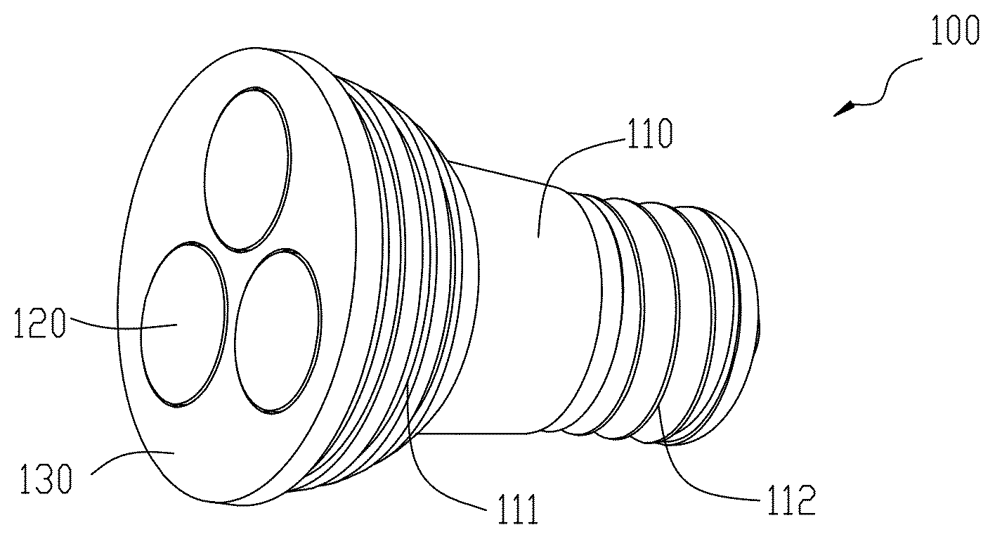
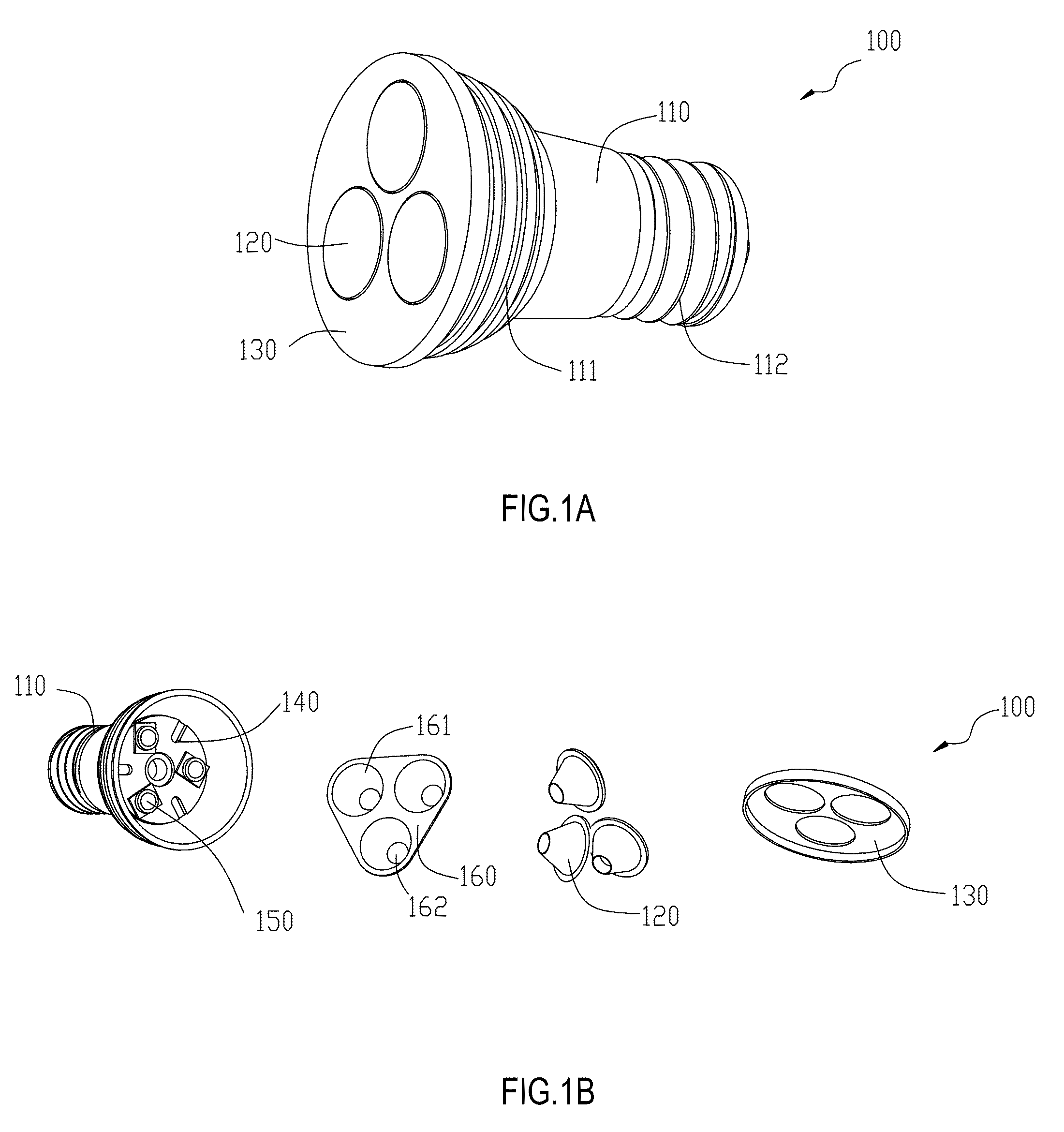
[0046]Included in embodiments of the invention are lamp assemblies that provide for various forms of light. More particularly, and as will be described further below, features of lamp assemblies according to the invention can include, for the MR 16 lamps, 12V AC / DC input; with a color temperature range of approximately 2800K to 7500K; a standard GU5.3 two-pin MR 16 base or othe...


PUM


Abstract

The present invention relates to lighting assemblies and more particularly to light emitting diode (LED) light bulbs comprising a support for one or more LED lenses, which can be used to position and support the lenses within the lamp housing and which facilitate assembly of the light bulbs during manufacturing.

Description

CROSS-REFERENCE TO RELATED APPLICATIONS[0001]This application relies on the disclosure and claims the benefit of the filing date of U.S. Provisional Application No. 61 / 091,072 filed Aug. 22, 2008, the disclosure of which is hereby incorporated by reference in its entirety.BACKGROUND OF THE INVENTION[0002]1. Field of the Invention[0003]The present invention relates to lighting assemblies and more particularly to light bulbs comprising a support for one or more light emitting diode (LED) lenses, which can be used to position and support the lenses within a lamp housing and which facilitate assembly of the light bulbs during manufacturing.[0004]2. Description of the Related Art[0005]Spot light type bulbs are well known and are available in many formats, including bulbs with halogen or LED light sources. Typical formats include MR and PAR series in various sizes. Very generally, the number of the series (for example, MR 16) corresponds with the number of eighth-inch increments in the di...

Claims


Application Information

Patent Timeline
Patent Type & Authority Applications(United States)
IPC IPC(8): F21V21/00H01J9/00F28F7/00
CPCF21Y2101/02F21Y2113/005F21K9/137F21V17/12F21K9/233F21Y2113/13F21Y2115/10
Inventor LI, QING CHARLESHUANG, YANGCHENGWANG, HAIJUNWEI, CUIEHUANG, GUOHONG
Owner US VAOPTO
Why Eureka
Try Eureka