Dc-dc converter
a converter and synchronous rectifier technology, applied in the direction of automatic control, process and machine control, instruments, etc., can solve the problems of increasing electric power consumption, dc-dc converters with synchronous rectifiers are susceptible to the occurrence of reverse currents, and increasing the power consumed by the cpu proportionally to the frequency of the clock
- Summary
- Abstract
- Description
- Claims
- Application Information
AI Technical Summary
Benefits of technology
Problems solved by technology
Method used
Image

Examples
first embodiment
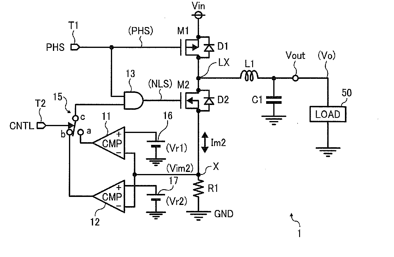
[0038]FIG. 1 illustrates circuitry of an output portion of a DC-DC converter 1 according to the present embodiment. The output portion of the DC-DC converter 1 includes comparators 11 and 12, an AND circuit 13, a switch 15, a first reference voltage source 16, a second reference voltage source 17, a switching transistor M1, a synchronous rectification transistor M2, a resistor R1, an inductor L1, and a capacitor C1. It is to be noted that a diode D1 is a dependent diode parasitic to the switching transistor M1, and a diode D2 is a dependent diode parasitic to the synchronous rectification transistor M2.
[0039]Further, the output portion of the DC-DC converter 1 includes a power input terminal Vin, an output terminal Vout, a ground terminal GND, and internal terminals T1 and T2. An input voltage V1 is applied between the power input terminal Vin and the grand terminal GND, and an output voltage Vo of the DC-DC converter 1 is outputted from the output terminal Vout, and thus, power is ...
second embodiment
[0087]Next, a second embodiment of the present invention is described below. FIG. 5 illustrates circuitry of an output portion of a DC-DC converter 1A according to the second embodiment.
[0088]In contrast to the first embodiment, in the second embodiment the resistor R1 is removed and the source of the synchronous rectification transistor M2 is directly connected to the ground terminal GND, and the inverting terminals of the comparator 11 and the comparator 12 are connected to a junction node LXA.
[0089]Then, in the second embodiment, the comparator 11 serves as the first voltage detector, and the comparator 12 serves as the second voltage detector. The remainder of the configuration is similar to that of the first embodiment, and therefore a description thereof is omitted.
[0090]The operation of the circuit in the present embodiment is described below with reference to FIG. 6, which is a timing chart of the operation in the second embodiment.
[0091]In FIG. 6, reference character VLXA r...
third embodiment
[0106]Next, a third embodiment of the present invention is described below. FIG. 7 illustrates circuitry of an output portion of a DC-DC converter 1B according to the third embodiment.
[0107]The third embodiment differs from the first embodiment in that the configuration shown in FIG. 7 includes one comparator 20 instead of the two comparators 11 and 12, and the switch 15 is disposed between a non-inverting input terminal of the comparator 20 and the first reference voltage Vr1 or the second reference voltage Vr2. An output terminal of the comparator 20 is connected to the second input terminal of the AND circuit 13, and an inverting terminal of the comparator 20 is connected to a junction node between the source of the synchronous rectification transistor M2 and the resistor R1. The comparator 20 serves as both a first reference voltage output device and a second reference voltage output device.
[0108]The circuit when the common contact c is connected to the contact a in the switch 1...
PUM
 Abstract
Description
Claims
Application Information
 - R&D
- Intellectual Property
- Life Sciences
- Materials
- Tech Scout
- Unparalleled Data Quality
- Higher Quality Content
- 60% Fewer Hallucinations
Browse by: Latest US Patents, China's latest patents, Technical Efficacy Thesaurus, Application Domain, Technology Topic, Popular Technical Reports.
© 2025 PatSnap. All rights reserved.Legal|Privacy policy|Modern Slavery Act Transparency Statement|Sitemap|About US| Contact US: help@patsnap.com