
Techniques for Adaptive Predistortion Direct Current Offset Correction in a Transmitter

a direct current offset and transmitter technology, applied in the direction of dc level restoring means or bias distorting correction, digital transmission, baseband system details, etc., can solve the problem of affecting the symbol recovery of a transmitted signal at a receiver, affecting the transmission of signals, and transmitters showing excessive spurious emissions

Active Publication Date: 2010-02-25
NXP USA INC
View PDF19 Cites 45 Cited by
  • Summary
  • Abstract
  • Description
  • Claims
  • Application Information

AI Technical Summary

Benefits of technology

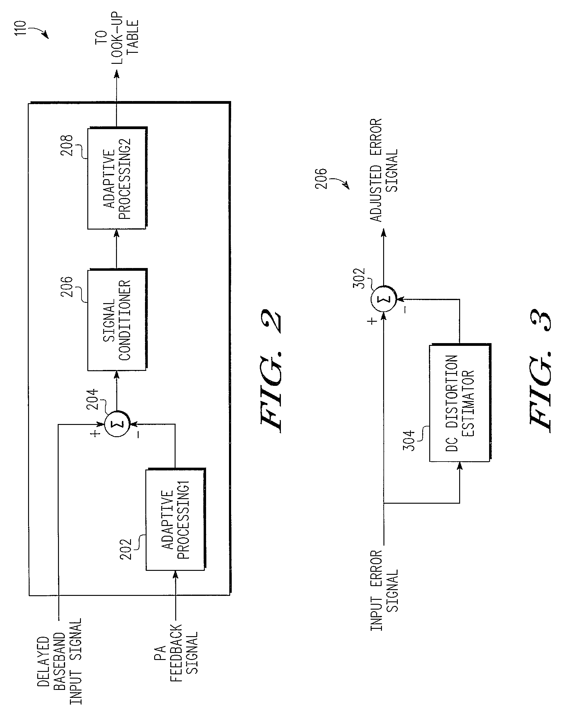
[0015]Advantageously, a signal conditioner configured according to one embodiment of the present disclosure removes residual DC, tracks DC variation, and introduces no delay in a transmit path of a transmitter. In various embodiments, the signal conditioner is independent of the feedback path, as well as other parts of the APD. Advantageously, the signal conditioner is configured to cope with any fine DC-related offset that is present in the feedback path. The signal conditioner ‘cleans’ and ‘fine-tunes’ the input error signal before it is further processed enabling a more accurate predistortion function to be selected, resulting in improved modulation output radio frequency spectrum (mod ORFS), improved adjacent channel leakage ratio (ACLR), and reduced out-of-band emissions.
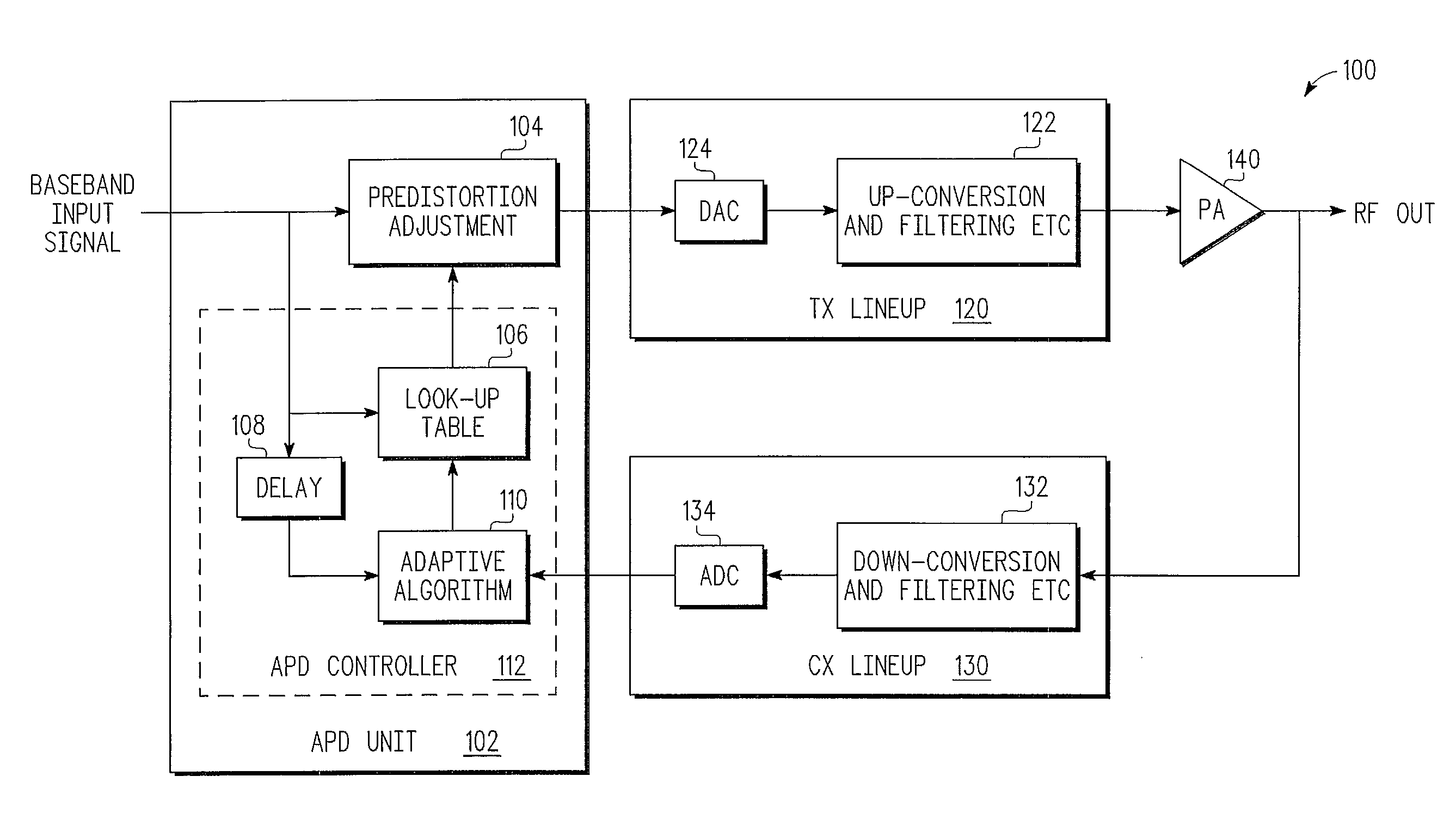
[0018]According to yet another embodiment of the present disclosure, a transmitter includes a power amplifier and an adaptive predistortion unit. The adaptive predistortion unit includes an error signal unit and a signal conditioner. The error signal unit (e.g., a summer) includes a first input (configured to receive a delayed version of a baseband input signal), a second input (configured to receive a power amplifier feedback signal from an output of a power amplifier), and an output (configured to provide an input error signal that corresponds to a difference between the delayed version of the baseband input signal and the power amplifier feedback signal). The signal conditioner includes an input configured to receive the input error signal and an output configured to provide an adjusted error signal that has a lower direct current offset than the input error signal. Accordingly, lowering the direct current offset associated with the input error signal reduces a transmitted signal distortion associated with the power amplifier.

Problems solved by technology

In general, due to technology limitations, power amplifiers (PAs) are inherently non-linear devices that may distort a signal to be transmitted causing adjacent channel leakage and out-of-band emissions.
Moreover, distortion attributable to PA non-linearity may hinder symbol recovery of a transmitted signal at a receiver.
Unfortunately, even a small direct current (DC) offset (after coarse DC offset correction) may cause a transmitter to exhibit excessive spurious emissions.
For example, a few millivolts DC offset in an APD feedback path of a transmitter may result in excessive out-of-band leakage (e.g., modulation output radio frequency spectrum (mod ORFS) figures) that may cause the transmitter to fail specifications.
Unfortunately, a DC offset may vary when a signal is modulated.
Unfortunately, the in-line low-pass filter technique inserts extra delay in a transmit path.

Method used


Image

  • Techniques for Adaptive Predistortion Direct Current Offset Correction in a Transmitter
  • Techniques for Adaptive Predistortion Direct Current Offset Correction in a Transmitter
  • Techniques for Adaptive Predistortion Direct Current Offset Correction in a Transmitter

Examples


Embodiment Construction

[0012]In the following detailed description of exemplary embodiments of the invention, specific exemplary embodiments in which the invention may be practiced are described in sufficient detail to enable those skilled in the art to practice the invention, and it is to be understood that other embodiments may be utilized and that logical, architectural, programmatic, mechanical, electrical, and other changes may be made without departing from the spirit or scope of the present invention. The following detailed description is, therefore, not to be taken in a limiting sense and the scope of the present invention is defined only by the appended claims and their equivalents. In particular, the embodiments described below may be embodied in various wired or wireless communication devices.

[0013]The disclosed techniques are contemplated to be applicable to systems that employ a variety of signaling techniques (e.g., orthogonal frequency division multiplex (OFDM), single-carrier frequency div...


PUM


Abstract

A technique for performing adaptive predistortion in a transmitter includes receiving, at a first input of an error signal unit, a delayed version of a baseband input signal. The technique also includes receiving, at a second input of the error signal unit, a power amplifier feedback signal from an output of a power amplifier. An input error signal that corresponds to a difference between the delayed version of the baseband input signal and the power amplifier feedback signal is then provided at an output of the error signal unit. The input error signal is then received at an input of a signal conditioner. An adjusted error signal that has a lower direct current offset than the input error signal is provided at an output of the signal conditioner.

Description

BACKGROUND[0001]1. Field[0002]This disclosure relates generally to adaptive predistortion and, more specifically, to techniques for adaptive predistortion direct current offset correction in a transmitter.[0003]2. Related Art[0004]In general, due to technology limitations, power amplifiers (PAs) are inherently non-linear devices that may distort a signal to be transmitted causing adjacent channel leakage and out-of-band emissions. Moreover, distortion attributable to PA non-linearity may hinder symbol recovery of a transmitted signal at a receiver. Adaptive predistortion (APD) is a known approach that has been utilized to address transmitter PA non-linearity. According to the APD approach, a function that represents an inverse of a PA transfer function is multiplied with a baseband input signal in order to linearize an overall PA gain at an output of the PA. Typically, predistortion is implemented in an adaptive closed-loop configuration in which a PA output signal is fed back to an...

Claims


Application Information

Patent Timeline
IPC IPC(8): H04B1/04
CPCH03F1/3247H03F2201/3233H04L27/366H04L25/06H04B1/0475
Inventor TANG, CLIVE K.XU, BING
Owner NXP USA INC
Learn More