
Heat exchanger made of aluminum alloy and method of producing same

Inactive Publication Date: 2010-03-04
CALSONIC KANSEI CORP +1
View PDF19 Cites 44 Cited by
  • Summary
  • Abstract
  • Description
  • Claims
  • Application Information

AI Technical Summary

Benefits of technology

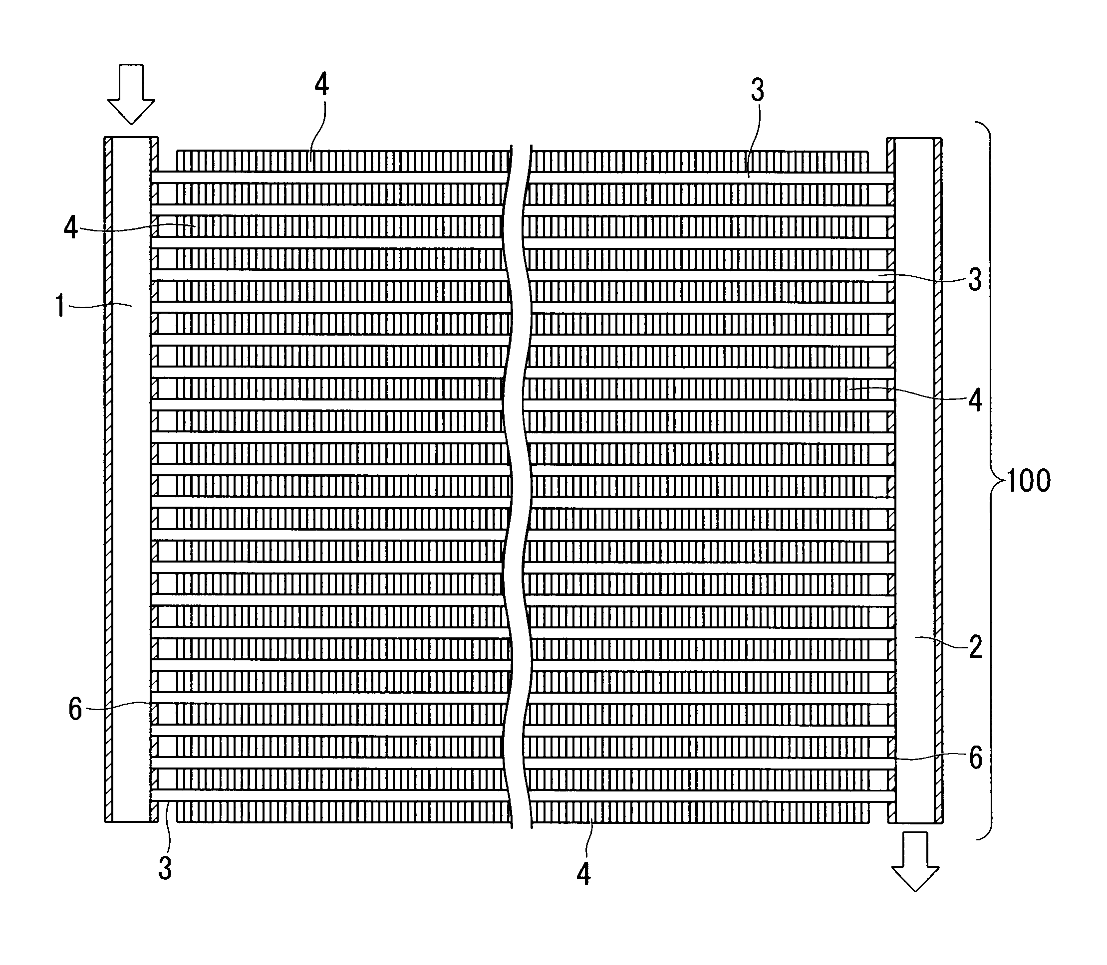
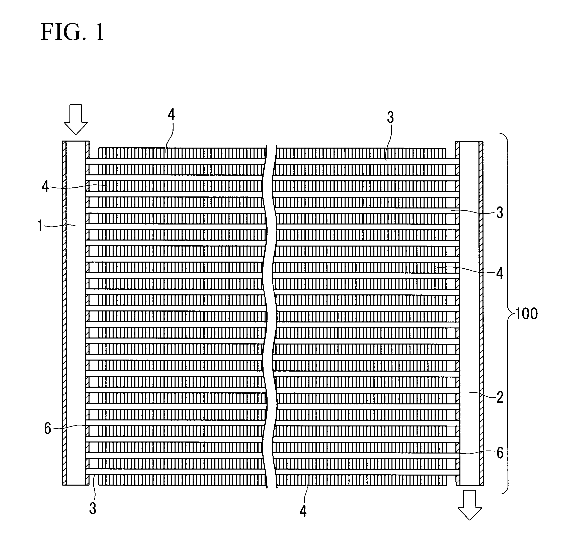
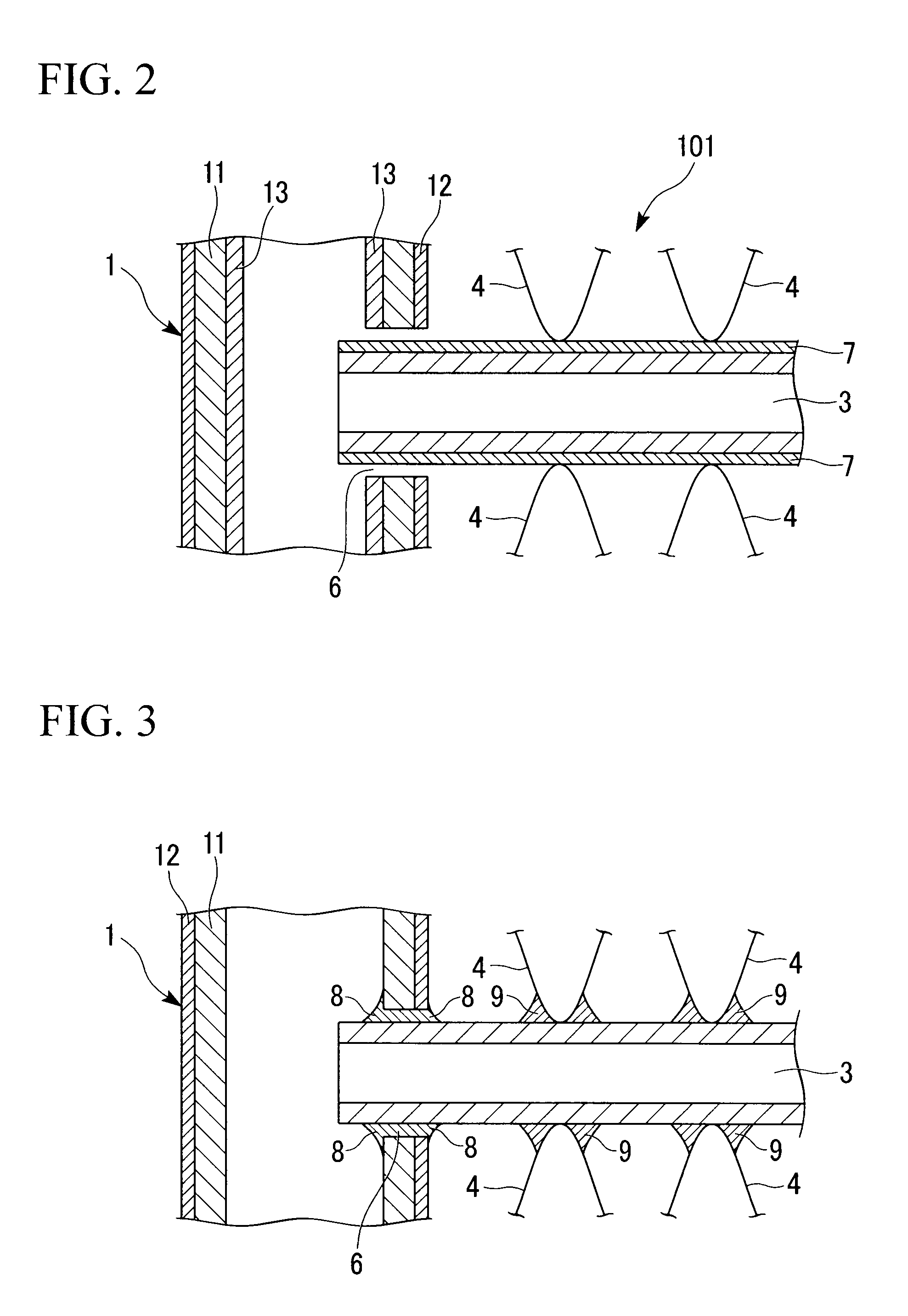
[0026]According to the heat exchanger of the present invention, the tube added with appropriate amounts of Mn and Si has a corrosion resistance superior to the conventional alloy such as 1050 alloy or Al—Cu based alloy. Therefore, it is possible to reduce the amount of Zn contained in the flux for forming a sacrificial corrosion protection layer. As a result, it is possible to reduce the amount of Zn flowing to the fillet with the brazing liquid filler, thereby suppressing the preferential corrosion of the fillet. Thus, it is possible to prevent separation of the fin.
[0035]During the heating process in the process of producing a heat exchanger according to the present invention, the assembled fin, tube, and fillet are held at an intermediate temperature range from 530 to 575° C. for 4 to 8 minutes, and subsequently heated to a brazing temperature. In this method, since the assembly is held for a predetermined duration at a temperature range at which flow of brazing liquid filler does not occur but diffusion of Zn to the tube does occur, it is possible to ensure sufficient diffusion of Zn into the tube wall of the tube. Therefore, it is possible to suppress the excessive concentration of Zn into the fillet. Therefore, it is possible to suppress the preferential corrosion of fillet, thereby suppressing separation of the fin from the heat exchanger.

Problems solved by technology

Such a potential gradient increases corrosion of the tube and causes pitting to occur, causing leakage of a refrigerant, and reducing the strength of the tube.
However, where the Zn-containing flux is used in the brazing, a large amount of Zn flows with the brazing liquid filler and concentrates to fillets joining fins and the tubes.
Where preferential corrosion of the fillets occurs, fins are separated from the tube surfaces, reducing heat transfer efficiency.
In such a case, the heat exchanger cannot keep sufficient efficiency.
However, according to further investigation by the inventors, it was discovered that preferential corrosion of fillets could not be avoided where large amount of Zn concentrates to fillets.
In such a case, even though the Zn concentration in the tube surface can be homogenized, a large difference in concentration of Zn between the fillet and the tube may causes preferential corrosion of the fillet.

Method used


Image

  • Heat exchanger made of aluminum alloy and method of producing same
  • Heat exchanger made of aluminum alloy and method of producing same
  • Heat exchanger made of aluminum alloy and method of producing same

Examples


example 1

[0126]An aluminum alloy having a composition shown in Table 1 was cast from molten alloy for constituting tubes, and aluminum alloy having a composition shown in Table 2 was cast from a molten alloy for constituting fins. For constituting header pipes, an aluminum alloy for core material, an aluminum alloy for sacrificial corrosion protection material, and an aluminum alloy for brazing material, each having a composition as shown in Table 3 were cast from molten alloys.

[0127]The aluminum alloy for a tube was subjected to heat treatment for homogenization, and was subsequently subjected to hot extrusion so as to have a shapes as shown in transversal cross section in FIG. 4 and FIG. 6A. In the tube shown in FIG. 4, the wall thickness was 0.30 mm, the width was 18.0 mm, the total thickness was 1.5 mm, the height of flat face of the side surface was 0.6 mm, and the curvature radius of the corner portion was 0.45 mm. In the tube shown in FIG. 6A, the wall thickness was 0.30 mm, the width...

example 2

[0148]Heat exchangers 100 were produced in the same manner as in Example 1, while the tubes were made of aluminum alloy having a composition shown in Table 5. The depth of corrosion in the tube 3 and the residual ratio of fins 4 were examined in the same manner as in Example 1. The results are shown in Table 5. In this case, brazing composition of No. 4 shown in Table 4 was applied as a coating composition.

TABLE 5Fin-tubeCorrosionResidualMnSijoint ratiodepth of tuberatio of finsTube(mass %)(mass %)Al(%)(μm)(%)Remark240.130.35balance9511580250.210.35balance967578260.300.35balance947276270.390.35balance957072280.470.35balance957273Excessive Mn,ReducedExtrudability290.300.15balance9610278300.300.26balance967275310.300.44balance957570320.300.52balance957572Excessive silicon,ReducedExtrudability

[0149]As shown in Table 5, the corrosion resistance of the tube 3 and the residual ratio of fins 4 vary depending on the Mn content and the Si content of the tube 3. Therefore, preferable contents...

example 3

[0150]Heat exchangers 100 were produced in a same manner as in Example 1, while the fins were made of aluminum alloy having a composition shown in Table 6. The depth of corrosion in the tube 3 and the residual ratio of fins 4 were examined in the same manner as in Example 1. The results are shown in Table 6. In this case, a brazing composition of No. 4 shown in Table 4 was applied as the coating composition.

TABLE 6Fin-tubeCorrosionResidualjointdepth ofration ofZnSiFeMnZrVCrratiotubefinsFin(mass %)(mass %)(mass %)(mass %)(mass %)(mass %)(mass %)(%)(μm)(%)Remark331.10.950.51.20.130.050.059510592341.30.950.51.20.13—0.05967574351.50.950.51.20.130.05—947078361.70.950.51.2—0.050.05957176372.00.950.51.20.13——959260381.50.60.51.20.13——9611361391.50.80.51.20.130.050.05967575401.51.10.51.20.130.050.05957378411.51.250.51.20.13——959060421.50.950.251.20.13——9410760431.50.950.411.20.130.050.05957280441.50.950.691.20.130.050.05967581451.50.950.851.20.13——948560461.50.950.50.850.130.050.05951057247...


PUM

PropertyMeasurementUnit
Temperatureaaaaaaaaaa
Linear densityaaaaaaaaaa

Abstract

A heat exchanger comprising a tube, a fin, and a header pipe, wherein the tube contains, in mass %, 0.15 to 0.45% of Mn, 0.20 to 0.50% of Si, and the balance of Al and unavoidable impurities, and is coated with a coating of brazing composition containing 1.0 to 5.0 g / m2 of Si powder, 4.0 to 10.0 g / m2 of KZnF3, and 0.5 to 3.0 g / m2 of binder; the fin contains, in mass %, 1.20 to 1.80% of Zn, 0.70 to 1.20% of Si, 0.30 to 0.80% of Fe, 0.90 to 1.50% of Mn, one or two or more selected from 0.05 to 0.20% of Zr, 0.01 to 0.10% of V, and 0.01 to 0.10% of Cr, and the balance of Al and unavoidable impurities; and the header pipe comprises a core material, outer sacrificial corrosion protection material, and an inner brazing material.

Description

BACKGROUND OF THE INVENTION[0001]1. Field of the Invention[0002]The present invention relates to a heat exchanger made of an aluminum alloy and a method of producing the same. Specifically, the present invention relates to a heat exchanger made of an aluminum alloy and a method of producing the same in which separation of fins from tubes can be suppressed.[0003]Priority is claimed on Japanese Patent Application No. 2008-225324, filed Sep. 2, 2008, the content of which is incorporated herein by reference.[0004]2. Description of Related Art[0005]Heat exchangers made of aluminum alloy comprises tubes, fins, and header pipes as main constituents. The heat exchangers are produced by brazing those constituents. Conventionally, brazing sheets clad with Al—Si alloy brazing material have been widely used in their production. Production cost of the heat exchanger has been reduced by using extruded tubes (hereafter referred to as tubes) having surfaces coated with a brazing composition compose...

Claims


Application Information

Patent Timeline
IPC IPC(8): F28F9/04F28F1/12
CPCB21D53/08B23K1/0012F28F9/06F28F21/084F28F2275/04F28D1/05366
Inventor SOGABE, MASAHIROFUNATSU, TAKUMISHINHAMA, MASAYOSHIHYOGO, YASUNORIKATSUMATA, MASAYAASANO, MASAMI
Owner CALSONIC KANSEI CORP
Learn More