Variable conductance heat pipe

a heat pipe and conductance technology, applied in semiconductor lasers, lighting and heating equipment, instruments, etc., can solve the problems of wasteful electric power use, long waiting time, and inconvenience for users

Inactive Publication Date: 2010-03-04
MITSUBISHI ELECTRIC CORP
View PDF6 Cites 39 Cited by
  • Summary
  • Abstract
  • Description
  • Claims
  • Application Information

AI Technical Summary

Benefits of technology

[0010]According to the above-described configuration, the variable conductance heat pipe can operate as a heat insulated type heat pipe with less electric power by heat being supplied to the heat receiving portion, the temperature of the heat receiving portion can be set to an arbitrary temperature based on the amount of noncondensable gas sealed in the variable conductance heat pipe, and the temperature of the element to be cooled provided in the heat receiving portion can easily be controlled to an arbitrary temperature.

Problems solved by technology

The larger the difference between the two temperatures is, the longer the waiting time becomes, which is not convenient for the user.
In a system having electronic equipment whose temperature needs to be controlled, although the temperature of the electronic equipment is desirably maintained in a state where the temperature lies in the vicinity of a set temperature at which the electronic equipment operates at all times in order to enable a quick output in response to a request from the user, when the temperature of the electronic equipment is maintained in such a state at all times, the consumed power that is necessary to do so becomes large, which results in a wasteful use of electric power.
In this approach, however, since equipment for detecting an input from the user and a control mechanism for enabling the detection are required, electric power for controlling them is required separately, and since the electronic equipment is heat controlled (heated) to the set temperature while heat is radiated from a heat radiating unit of the electronic equipment, the reduction effect of consumed power is not as high as expected.
In addition, although there is an approach in which a temperature control speed at which the temperature of electronic equipment is controlled to its set temperature is made faster by employing high-performance heating and cooling units, a high-level control with a short response time becomes necessary, and such a control is difficult to be applied to electronic equipment which is small in size.

Method used


Image

  • Variable conductance heat pipe
  • Variable conductance heat pipe
  • Variable conductance heat pipe

Examples


embodiment 1

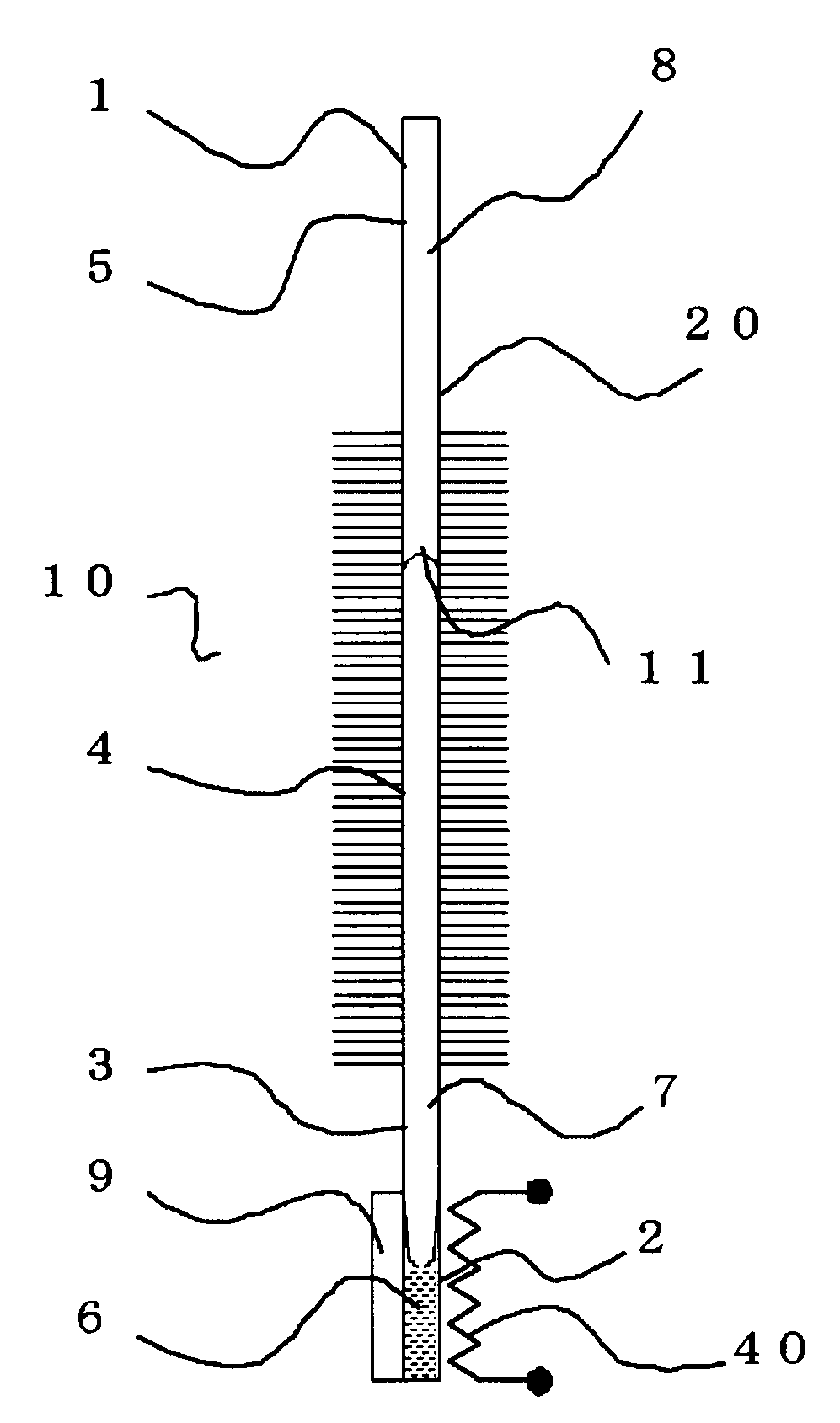
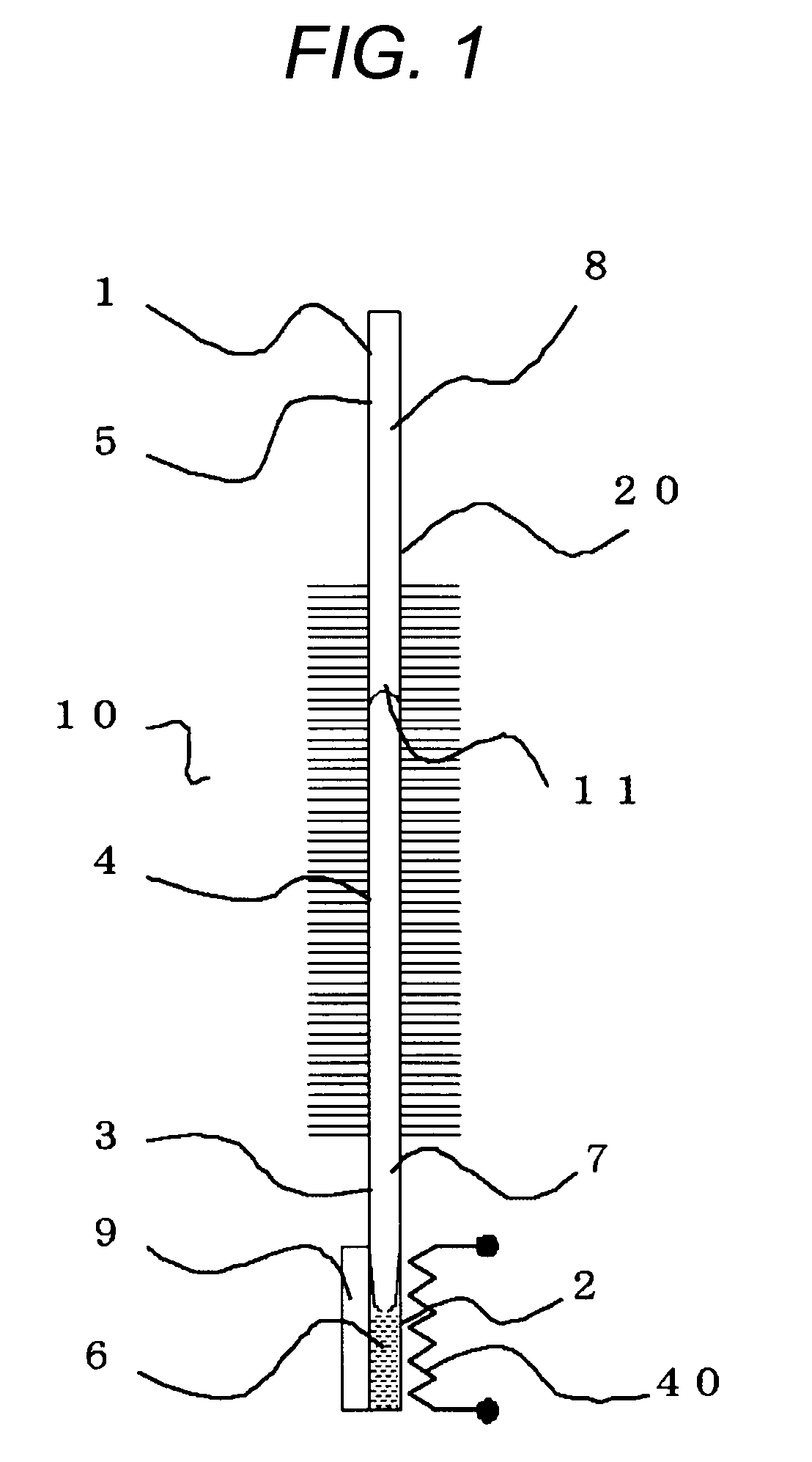
[0017]FIG. 1 is a sectional view showing a variable conductance heat pipe according to Embodiment 1 of the invention. As shown in FIG. 1, from one end portion, a variable conductance heat pipe 20 includes a sealed container 1 are a heat receiving portion 2 (an evaporating portion), a heat insulating portion 3 (a transporting portion), a heat radiating portion 4 (a condensing portion) and a noncondensable gas reservoir portion 5. A working fluid (a liquid 6 and vapor 7 thereof) and a noncondensable gas 8 are sealed in an interior of the sealed container 1. A heater 40 and an element to be cooled 9 are provided to the heat receiving portion 2.

[0018]Next, the operation of the variable conductance heat pipe of the Embodiment 1 will be described. When the element to be cooled 9 is activated to operate to obtain a desired function of the element to be cooled 9, heat is generated in an interior of the element to be cooled 9, whereby the temperature of the element to be cooled 9 is raised. ...

embodiment 2

[0033]FIG. 3 is a diagram showing the configuration of Embodiment 2 of the invention. While in Embodiment 1, the temperature of the heat receiving portion 2 can be set to an arbitrary temperature with less energy, when a main part 12 (of which the temperature needs to be controlled) in the element to be cooled 9 lies away from the heat receiving portion 2 (when a thermally interposed material 13 is interposed therebetween), even in Embodiment 1, there is generated a difference in temperature which corresponds to a thermal resistance of the thermally interposed material 13 is generated when the element to be cooled 9 is not in operation. Then, in Embodiment 2, by providing a heater 40 near a main part 12 in the element to be cooled 9, a difference in temperature which is generated by a heat input from the heater 40 and the thermal resistance of a thermally interposed material 13 can be compensated for, thereby making it possible to reduce a difference in temperature between when the ...

embodiment 3

[0036]FIG. 4 is a diagram showing the configuration of Embodiment 3 of the invention. In this configuration, a fan 14 is provided for forcing a cooling fluid to flow through a heat radiating portion 4 of a variable conductance heat pipe 20, an element to be cooled 9 is provided within a temperature sensor 15, and the fan 14 and the heater 40 are controlled with respect to outputs thereof by the temperature sensor 15 and a control circuit 16, so as to provide an optimum temperature control. The fan 14 may be a pump which causes the cooling fluid to flow to the heat radiating portion. Namely, the fan 14 may take any form, as long as it remains a cooler for cooling the heat radiating portion 4.

[0037]By adopting this configuration, the temperature of the element to be cooled 9 can be controlled through heating / cooling via the variable conductance heat pipe 20, whereby not only can a transition time to a set temperature and a waiting time of the user be shortened, but also the temperatur...


PUM


Abstract

A variable conductance heat pipe is provided. The variable conductance heat pipe includes a sealed container in which a working fluid and a noncondensable gas are sealed. The sealed container includes a heat receiving portion to which an element to be cooled is provided, and heat radiating portion. An amount of heat is supplied to the heat receiving portion when the element to be cooled is in a waiting state.

Description

CROSS-REFERENCE TO RELATED APPLICATION[0001]This application claims priority from Japanese Patent Application No. 2008-219550, filed on Aug. 28, 2008, the entire subject matter of which is incorporated herein by reference.BACKGROUND OF THE INVENTION[0002]1. Field of the Invention[0003]The present invention relates to a variable conductance heat pipe for maintaining the temperature of equipment not in operation at an arbitrary temperature with small electric power.[0004]2. Description of the Related Art[0005]In a projector and a printer, in order to operate desirably, the temperature of a main part such as a light source has to be controlled to an appropriate temperature. As a temperature controller for maintaining the temperature of such a main part of a projector or printer to a temperature suitable for a desired function, there has been proposed a heater-type temperature controller for implementing a heat control through heating by a heater, a heat pump-type temperature controller...

Claims


Application Information

Patent Timeline
Patent Type & Authority Applications(United States)
IPC IPC(8): F28F27/00F28D15/02
CPCF28D15/06H01S5/02469F28F13/14G03F7/70891
Inventor IPPOSHI, SHIGETOSHINAGAYASU, TETSUYAHIRONAKA, SHINGOKITAZAKI, KURAKISATO, YUKIO
Owner MITSUBISHI ELECTRIC CORP
Why Eureka
Try Eureka