Unmanned air vehicle

a technology of unmanned aircraft and airframe, which is applied in the direction of aircraft stabilisation, aircraft navigation control, anchoring installation, etc., can solve the problems of obvious limitations in storage and launch features, and achieve reliable return flight and capture, wide range of different configurations, and easy launch

Inactive Publication Date: 2010-03-04
ISMAILOV ANVAR +1
View PDF16 Cites 71 Cited by
  • Summary
  • Abstract
  • Description
  • Claims
  • Application Information

AI Technical Summary

Benefits of technology

[0007]A specific advantage of the present invention is that the UAV possesses the attribute of ease of mobility within its own compact storage pod.
[0008]Aother advantage of the present invention is that the UAV is modularly assembled in a customized fashion to suit the specific mission needs, and therefore has a relatively wide range of different configurations readily available.
[0009]Another advantage of the present invention is that the UAV has foldable wings which are capable of assuming a substantially delta configuration in the folded mode when viewed along the fuselage of the UAV and which in the opened deployed mode display a substantially delta wing contour in plan view.
[0010]A further advantage of the present invention is that the UAV is easy to launch from any suitable site and moreover is capable of reliable return flight and capture.
[0011]An additional advantage of the present invention is that the UAV is self-powered during launch, typically with a jettisoned jet engine, and in outbound flight via at least one flight power engine, and preferably has a separate return power unit for the return flight.
[0012]An associated advantage of the present invention is the provision of a landing deck for receiving the returning UAV following an airborne mission.

Problems solved by technology

Although the monoplane is relatively simply constructed and capable of easy assembly with the facility of short take off and landing for short missions and also for longer range, it has certain obvious limitations in terms of its storage and launch features.

Method used


Image

  • Unmanned air vehicle
  • Unmanned air vehicle
  • Unmanned air vehicle

Examples


Embodiment Construction

[0040]With reference to the annexed drawings the preferred embodiment of the present invention will be herein described for indicative purpose and by no means as of limitation.

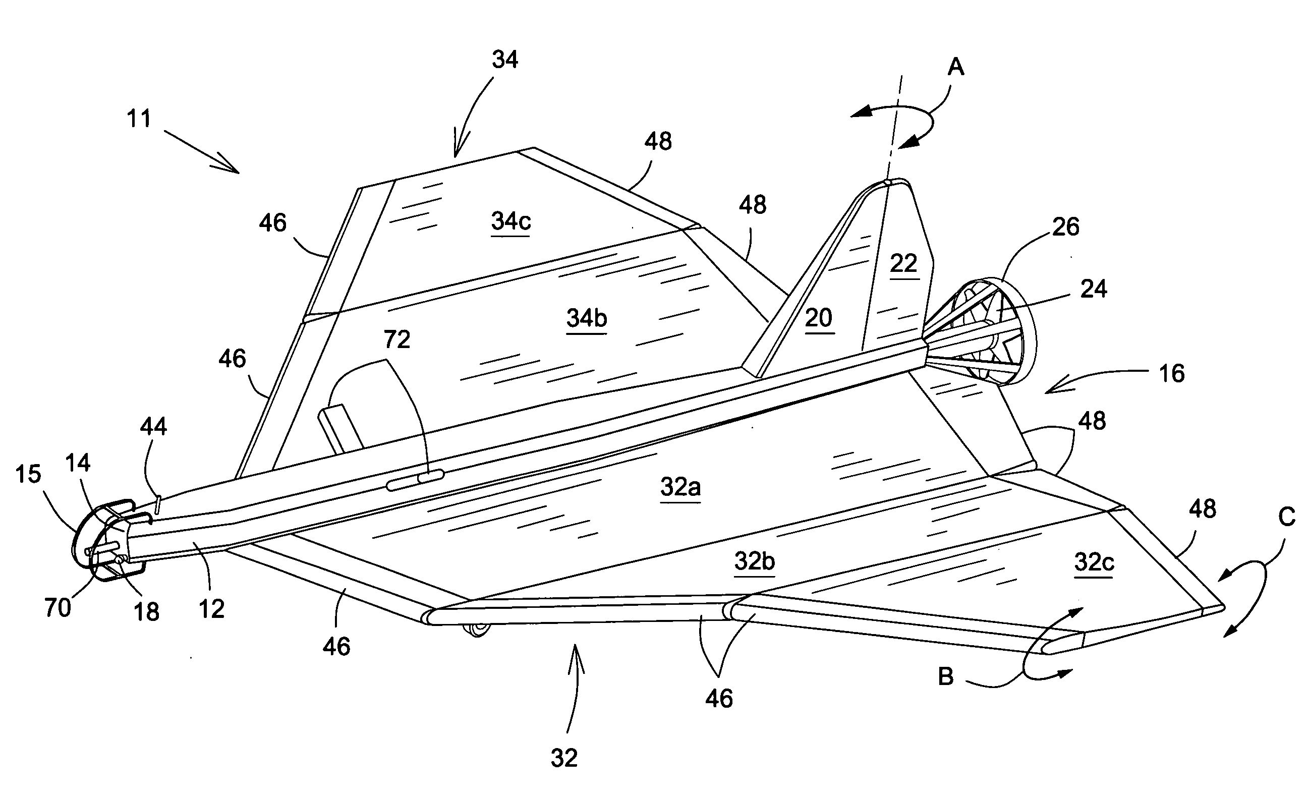
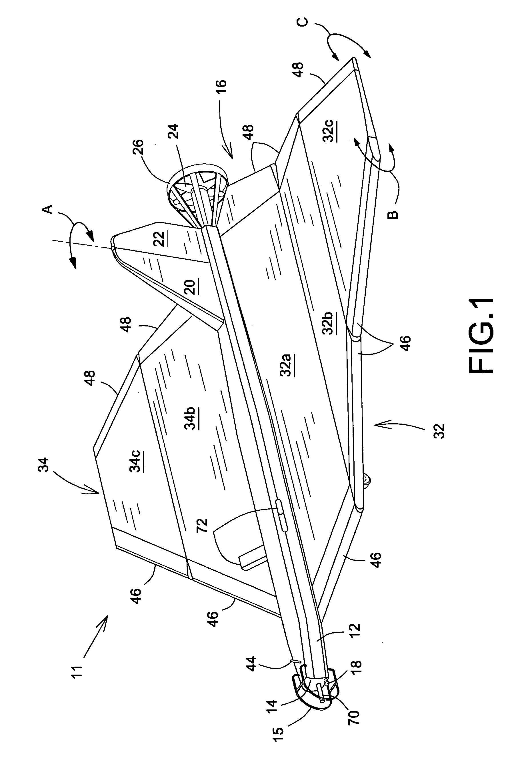
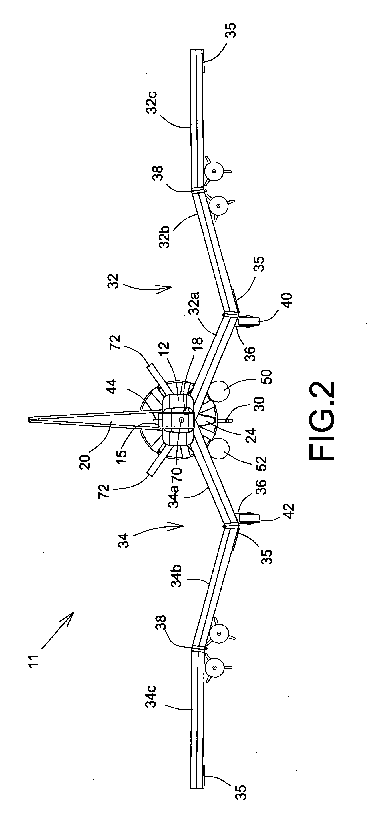
[0041]Referring to FIGS. 1 to 7, there is illustrated generally at 11 an unmanned air vehicle (UAV) having a fuselage 12 with a nose section 14 having a protective cage 15 and a tail section 16, the former incorporating inter alia reconnaissance or surveillance equipment in the form of a preferably gimbaled camera 18 or the like sensing equipments and the latter having mounted thereon a tail plane 20 provided with an angularly controllable rudder 22 (see arrow A in FIG. 1). The tail section 16 also has mounted at its end a propeller 24 within a nacelle 26 to which latter is releasably attached a launch jet engine 28 (FIGS. 3, 7 and 10), the latter allowing vehicle launches from aboard flying helicopters, if required. A landing hook 30 depends from the nacelle 26 as seen in FIG. 3 and functions as herein after ...


PUM


Abstract

An unmanned air vehicle for military, land security and the like operations includes a fuselage provided with foldable wings having leading edge flaps and trailing edge ailerons which are operable during ascent from launch to control the flight pattern with the wings folded, the wings being deployed into an open unfolded position when appropriate. The vehicle is contained within a pod from which it is launched and a landing deck is provided to decelerate and arrest the vehicle upon its return to land.

Description

FIELD OF THE INVENTION[0001]The present invention concerns an unmanned air vehicle (UAV) falling within the generic field of mobile robotic vehicles (MRV).[0002]In particular, but not exclusively the present invention has reference to a UAV suitable for deployment in military and / or land security operations, specifically offensive operations in battles zones or theatres of war. Such UAVs are armed with weaponry for battlefield use. It is to be understood, however, that as with some conventional UAVs the present invention may be employed for reconnaissance, surveillance or indeed meteorological surveying and accordingly the invention is not limited to offensive ballistics.BACKGROUND OF THE INVENTION[0003]There are many and varied forms of UAVs currently available, but one among many important requirements is the mobility of the UAV and its ease of launch characteristics.[0004]One proposal for a UAV is disclosed in U.S. patent Application Publication No. US 2008 / 0149758 to Colgren et ...

Claims


Application Information

Patent Timeline
Patent Type & Authority Applications(United States)
IPC IPC(8): B64C1/00B64C3/38B64D37/04B64F1/04B64C11/00B64D27/24B64D27/00G05D1/02F41A9/00F42B15/00B64F1/02B64F1/00F02K7/00
CPCB64C39/024B64C2201/021B64C2201/084B64C2201/102B64C2201/121B64C2201/208B64C2201/165F42B10/14F42B10/64B64C2201/201B64C2201/127B64U70/70B64U10/25B64U30/12B64U2101/15B64U2101/30B64U50/13B64U80/70B64U80/86
Inventor ISMAILOV, ANVAR
Owner ISMAILOV ANVAR
Why Eureka
Try Eureka