Wind energy installation with negative sequence system regulation and operating method
Active Publication Date: 2010-03-04
SENVION DEUT GMBH
1 Cites 41 Cited by
AI-Extracted Technical Summary
Problems solved by technology
However, difficulties can occur in the event of unbalanced grid faults.
Such oscillations load the rotor-generator system and increase the risk of failure of a wind energy installation.
However, that is confronted by a disadvantage, namely that larger ...
Method used
[0034]During normal operation of the wind energy installation, as much active current as possible is provided in the positive phase sequence system. As a result, depending on the wind conditions respectively prevailing, a maximum amount of compensated power is intended to be fed into the grid 99. The active component in the negative phase sequence system is intended to be reduced to zero as far as possible, in order to counteract harmful and material-loading 100 Hz oscillations of the drivetrain. By contrast, the reactive component of the negative phase sequence system is intended to be regulated to a maximum permissible value for the wind energy installation or the grid 99. By virtue of the power observer 81, provision can be made for varying the currents in the negative phase sequence system depending on the loading state of the wind energy installation. Thus, it may be provided that when the wind is strong and there are therefore (at least temporarily) high currents in the positive phase sequence system, only little or no feeding at all of neither active nor reactive component in the negative phase sequence system takes place. Therefore, precisely in times when there is a high load, it is pos...
Benefits of technology
[0006]The invention is based on the object of improving wind energy installations of the type mentioned in th...
Abstract
A wind energy installation can include a generator which is driven by a rotor and generates electrical power in a multiphase manner for feeding into a network, a converter which is connected to the generator and to the network, and a control system which interacts with the converter and includes a negative sequence system regulation mechanism. The negative sequence system regulation mechanism can include a phase control module configured to determine an electrical variable of the negative sequence system according to the phase. Accordingly, an available current can be provided according to the operating situation for active power or idle power in the negative sequence system regulation mechanism. The negative sequence system regulation mechanism can thus help stabilize the network in the event of asymmetrical network conditions. Also, this relates to a correspondingly equipped wind park and an operating method.
Application Domain
Wind motor controlEngine fuctions +9
Technology Topic
Automotive engineeringElectric generator +5
Image
Examples
- Experimental program(1)
Example
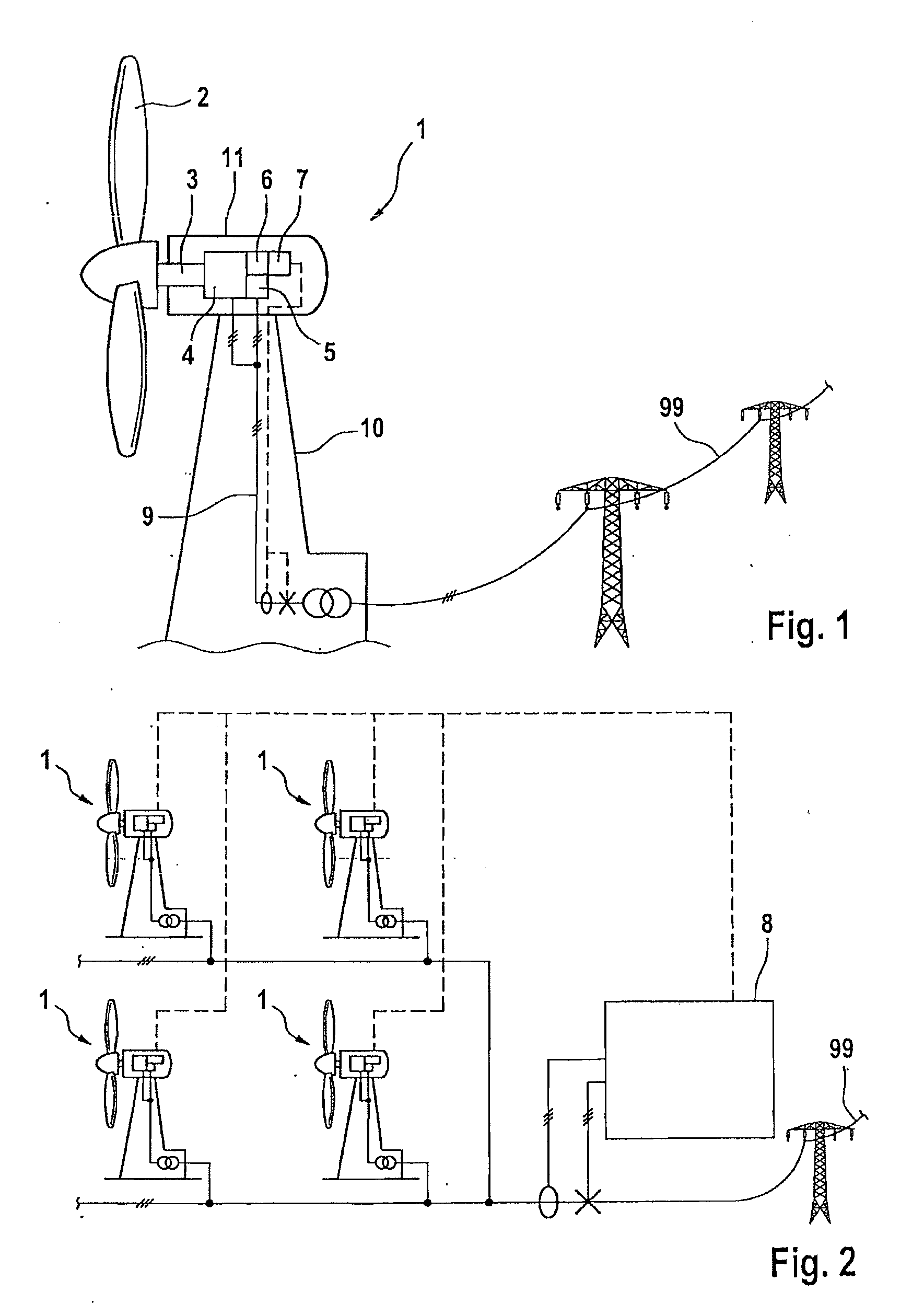
[0024]A wind energy installation 1 in accordance with one exemplary embodiment of the invention is illustrated in FIG. 1. It comprises a machine house 11 arranged rotatively on a tower 10, a rotor 2 being arranged rotatively at one end of said machine house. Said rotor drives a generator 4 via a rotor shaft 3, said generator being embodied as a doubly fed asynchronous generator in the exemplary embodiment illustrated. The generator is connected by its stator to connecting lines 9 connected to a supply grid 99 via an optional transformer. A converter 5 is furthermore provided, via which the rotor of the generator is connected to the connecting lines 9.
[0025]A controller 6 is provided, which is designed for controlling the operation of the wind energy installation. It is connected to the components of the wind energy installation via signal lines (not specifically illustrated). The controller 6 has a communication interface, with the result that remote control via telephone or data lines is made possible. Furthermore, in the case of a wind energy installation installed in a wind farm, the communication interface serves for communication with a wind farm master 8. In particular, the controller 6 serves for controlling the converter 5 and has a converter control module 7 for this purpose. The invention does not show external compensation modules possibly present (e.g. Statcom, SVC), which may likewise be present as reactive power sources in the wind farm.
[0026]order to elucidate the construction and the functioning of the converter control module 7, reference is made to FIG. 3, in particular. Measuring sensors for voltage and current are arranged on the connecting lines 9 leading to the grid 99. The measurement values are applied to inputs of the converter control module 7. A signal for the phase θ in the grid 99 or the connecting lines 9 is furthermore applied to an input. A coordinate transformation into a rotating system is carried out in an input stage of the converter control module 7. A block 71 for the transformation of the voltage values and a block 72 for the transformation of the current values are provided for this purpose. The transformation is effected in a manner known per se into a system rotating synchronously with the phase (positive phase sequence system) and an oppositely rotating system (negative phase sequence system). In this case, balanced components of voltage and current in the positive phase sequence system are represented as DC components, and unbalanced components as an AC component having a frequency corresponding to double the grid frequency (that is to say 100 Hz in the case of 50 Hz grids and 120 Hz in the case of 60 Hz grids). This AC component will be referred to as 100 Hz component hereinafter. Unbalanced components of voltage and current are represented in the negative phase sequence system as DC components, and balanced components as 100 Hz components. The 100 Hz components can be filtered out by means of corresponding filters (low-pass filter, band-pass filter, etc.). Only DC values in the positive and negative phase sequence systems (identified by index letters p and n, respectively) are then output at the output of the blocks, to be precise as so-called d,q coordinates. The block 71 outputs the voltage values in the positive and negative phase sequence systems and the block 72 outputs the current values in the positive and negative phase sequence systems.
[0027]From the values for voltage and current transformed into the d,q coordinate system, the voltage and current values of the positive phase sequence system are applied to a positive phase sequence system regulation block 73. In terms of its construction and function, the positive phase sequence system regulation block 73 largely corresponds to the regulation provided in conventional wind energy installations without negative phase sequence system regulation. A more detailed explanation is therefore unnecessary. The voltage and current values of the negative phase sequence system are applied to a negative phase sequence system regulation block 74. It comprises a phase module 75, which provides a signal regarding the phase θ in the grid for the negative phase sequence system regulation block. Details about the embodiment of the negative phase sequence system regulation block 74 are explained further below.
[0028]At its output, the negative phase sequence system regulation block provides actuating signals for active and reactive components Iw_n and Ib_n of the current in the negative phase sequence system and also a value for a reactive current Ib_p in the positive phase sequence system. The latter interacts with output signals of the positive phase sequence system regulation block 73 embodied in a manner known per se. The output signals of the two regulation blocks are converted in each case separately into a stationary two-dimensional coordinate system taking account of the phase θ in the grid by means of inverse transformation blocks 77, 78. In this coordinate system, the values for the positive and negative phase sequence systems are added at a summation element 79, and finally converted into the three-phase system by means of a further coordinate conversion block 80, and applied as control signals to the converter, to put it more precisely a pulse width modulator 55 controlling the converter 5.
[0029]For further elucidation of the regulation blocks 73, 74, reference is made to FIG. 4. Inputs for a plurality of desired signals are additionally illustrated, to be precise a desired value—functioning as a limit value—for the active component of the current in the negative phase sequence system (IwMax_n), a desired value for the active power in the positive phase sequence system (Ps_p), a desired value—functioning as a limit value—for the voltage in the negative phase sequence system (UMax_n) and a desired value for the voltage in the positive phase sequence system (Us_p).
[0030]The regulation blocks 73, 74 respectively have a regulator core 83, 84 containing a section model in each case. The separate embodiment for positive and negative phase sequence systems means that it is possible that, for the negative phase sequence system, a different section model is provided in the regulator core 84 of the negative phase sequence system than in the regulator core 83 of the positive phase sequence system. As a result it is possible in particular to take account of differences between positive and negative phase sequence systems such as arise for example from a frequency-dependent rotor resistance of the generator 4.
[0031]A power observer 81 is furthermore provided. It serves to determine still permissible limit values for active current and reactive current depending on the load state of the wind energy installation, to be precise expediently both for the positive phase sequence system and for the negative phase sequence system. At the power observer 81 there are inputs for the reactive current in the negative phase sequence system Ib_n, for the reactive current in the positive phase sequence system Ib_p and for the voltage value in the positive phase sequence system U_p. A limit value signal for a permissible maximum current I_max is furthermore provided. The power observer 81 determines therefrom the active power output by the wind energy installation and furthermore calculates limit values for the reactive and active components in the negative phase sequence system and positive phase sequence system taking account of the permissible maximum current I_max. The limit values are applied to corresponding limiter modules 85, 86, 87 and 88. Output signals are reactive and active components in positive and negative phase sequence systems Ib_p, Ib_n, Iw_p and Iw_n. Furthermore, the power observer 81 comprises a threshold value switch, which tolerates unbalances within a specific voltage band AU and in this respect deactivates the negative phase sequence system regulation.
[0032]A priority module 82 is assigned to the regulator cores 83, 84. It is designed, in interaction with the power observer 81 and a grid fault detector 80, to perform a weighing up of the current components in the negative phase sequence system, and preferably also in the positive phase sequence system.
[0033]The method of operation is as follows here:
[0034]During normal operation of the wind energy installation, as much active current as possible is provided in the positive phase sequence system. As a result, depending on the wind conditions respectively prevailing, a maximum amount of compensated power is intended to be fed into the grid 99. The active component in the negative phase sequence system is intended to be reduced to zero as far as possible, in order to counteract harmful and material-loading 100 Hz oscillations of the drivetrain. By contrast, the reactive component of the negative phase sequence system is intended to be regulated to a maximum permissible value for the wind energy installation or the grid 99. By virtue of the power observer 81, provision can be made for varying the currents in the negative phase sequence system depending on the loading state of the wind energy installation. Thus, it may be provided that when the wind is strong and there are therefore (at least temporarily) high currents in the positive phase sequence system, only little or no feeding at all of neither active nor reactive component in the negative phase sequence system takes place. Therefore, precisely in times when there is a high load, it is possible to avoid an overloading of the converter 5, for example by excessively high currents or excessively high voltage amplitudes in the intermediate circuit of the converter 5. The following priority thus arises: the highest priority is accorded to the feeding of active current in the positive phase sequence system, to be precise generally according to stipulation by a superordinate regulation mechanism. The second highest priority is accorded to providing reactive current in the positive phase sequence system for the voltage or frequency regulation in the grid 99. The third priority is accorded to the active current in the negative phase sequence system in order to reduce oscillations. The current remaining for the negative phase sequence system is calculated from the difference between the current in the positive phase sequence system and the permissible maximum current. Finally, the fourth priority is accorded to a further reduction of the voltage of the negative phase sequence system. The magnitude of the reactive current available for this in the negative phase sequence system is determined from the vectorial difference between the remaining current and the active current component thereof.
[0035]In the case of a grid fault, which may either be identified by the grid fault detector 80 or be indicated by a corresponding signal from a wind farm master or a control center of the grid operator, a different division of the current is provided by virtue of the priority module 82. Depending on the grid fault and the present operating point, the priority module 82 distinguishes between the priority of grid stabilization or installation preservation. If the priority module prescribes installation preservation, as a priority active current is supplied in the positive phase sequence system in order to be able to correct oscillations in the drivetrain and/or rotational speed changes. If the priority module prescribes grid stabilization, as a matter of priority reactive current is supplied in the positive and negative phase sequence systems, depending on balanced and unbalanced components of the voltage that occurs. A weighing up between the reactive current in the positive phase sequence system Ib_p and the reactive current in the negative phase sequence system Ib_n is performed. While the former has a voltage-stabilizing effect in the grid, the latter provides for a reduction of voltage unbalances. The weighing up can be carried out by means of a table, a family of characteristic curves, a system model or by means of a formula. The ratio of reactive current in the positive phase sequence system to the reactive current in the negative phase sequence system can be calculated as in the following example (with normalized variables)
I b_p = 0.5 · I b_n = 0.7 kI = I b_p I b_n
[0036]The division of the available current between reactive current in the positive phase sequence system and reactive current in the negative phase sequence system is effected with
I = I p + I n I p = I w_p 2 + I b_p 2 I n = I b_n = I b_p kI I = I w_p 2 + I b_p 2 + I b_p kI
[0037]Therefore, in the event of a fault, it is possible to achieve both good stabilization in the grid and effective damping of the drivetrain with respect to the harmful 100 Hz oscillations.
PUM


Description & Claims & Application Information
We can also present the details of the Description, Claims and Application information to help users get a comprehensive understanding of the technical details of the patent, such as background art, summary of invention, brief description of drawings, description of embodiments, and other original content. On the other hand, users can also determine the specific scope of protection of the technology through the list of claims; as well as understand the changes in the life cycle of the technology with the presentation of the patent timeline. Login to view more.