Digital Oscilloscope Module with Glitch Detection

a digital oscilloscope and glitch detection technology, applied in the field of diagnostic equipment, can solve the problems of high processing power of the display subsystem, high processing cost, and inability to acquire, transfer and display data at the desired rate, and achieve the effect of reducing the number of samples that can be transferred at an acceptable refresh rate, and reducing the processing cos

Active Publication Date: 2010-03-04
BOSCH AUTOMOTIVE SERVICE SOLUTIONS
View PDF16 Cites 33 Cited by
  • Summary
  • Abstract
  • Description
  • Claims
  • Application Information

AI Technical Summary

Benefits of technology

[0007]Embodiments of the present invention provide a digital oscilloscope with glitch detection that includes a synchronous random access memory (RAM), a digital signal processing unit, coupled to the synchronous RAM, and a master control unit coupled to the digital signal processing unit. The digital signal processing unit includes an analog-to-digital (A/D) converter to digitize an analog signal and a digital signal processor. The digital signal processor includes a dual-port RAM, a plurality of processing blocks to process the digitized analog signal data, detect glitches in the di...

Problems solved by technology

Unfortunately, high-speed data transfer requires expensive components and commensurately high processing power on the display subsystem.
Conversely, if a moderate or slow speed communication link is used, such as, for example, USB 1.1 or USB 2.0 “full speed,” RS-232, WiFi, Bluetooth, etc., the number of samples that can be transferred at an acceptable refresh rate is much more lim...

Method used


Image

  • Digital Oscilloscope Module with Glitch Detection
  • Digital Oscilloscope Module with Glitch Detection
  • Digital Oscilloscope Module with Glitch Detection

Examples


Embodiment Construction

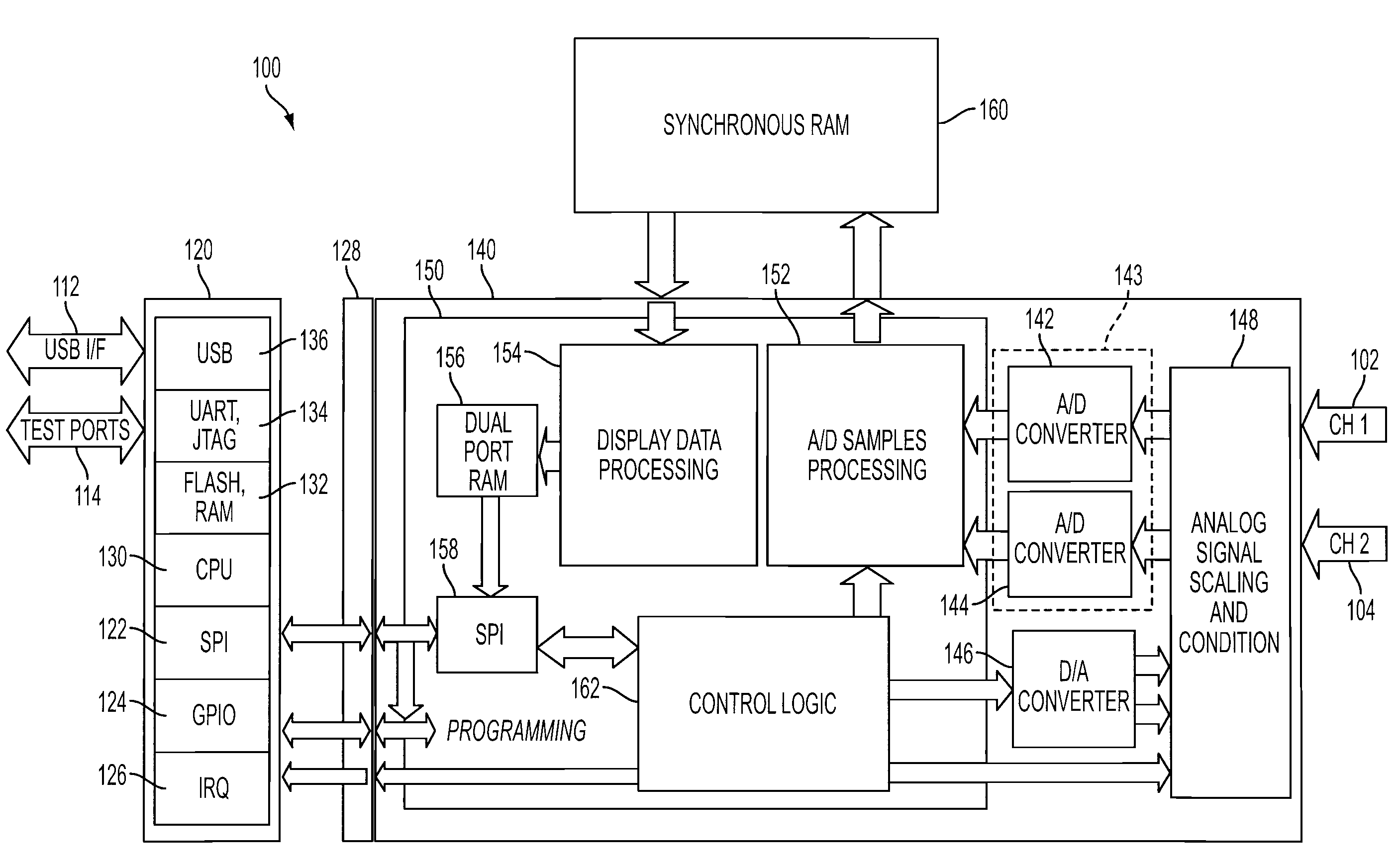
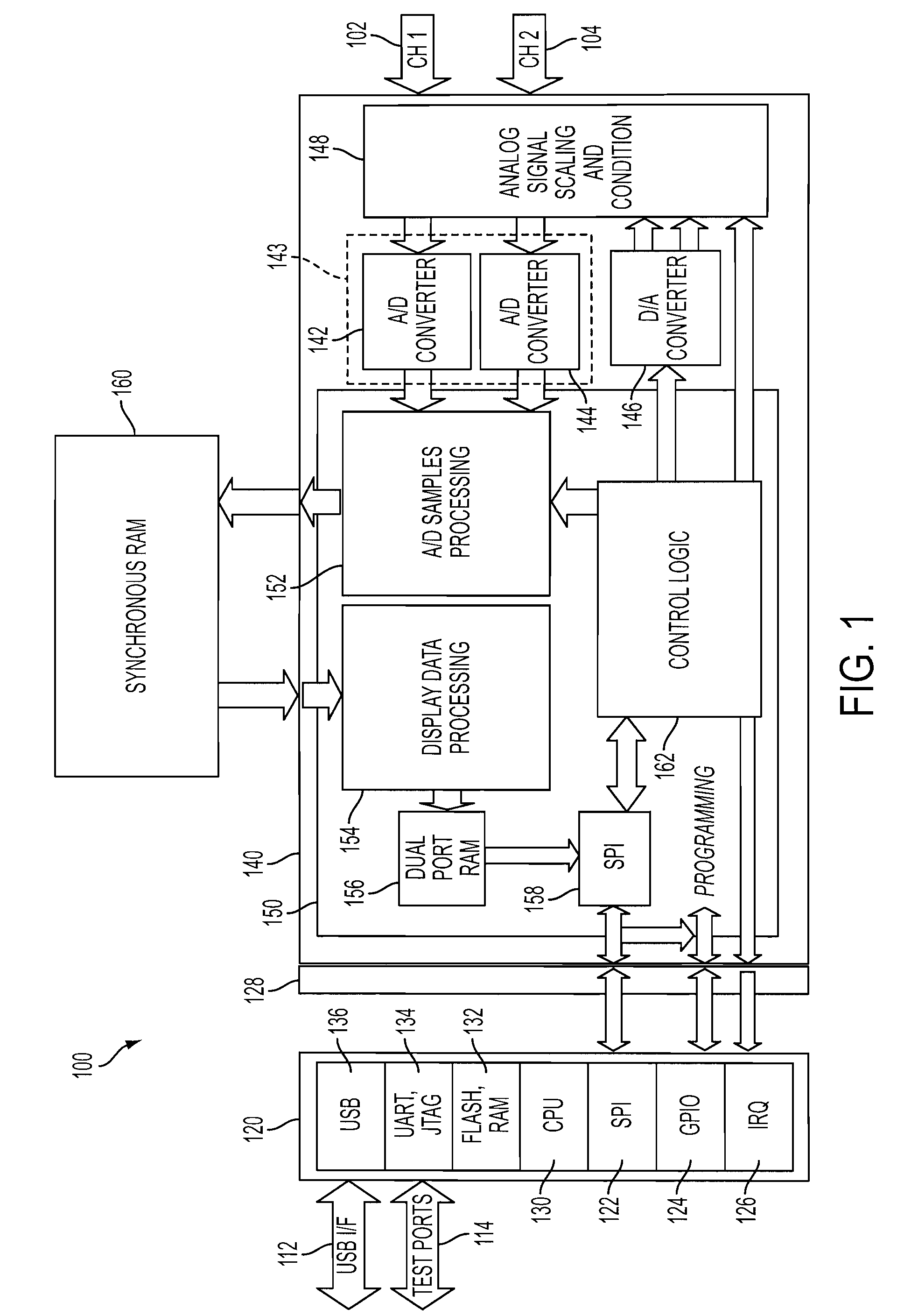
[0014]FIG. 1 is a schematic block diagram illustrating a digital oscilloscope module 100, in accordance with an embodiment of the present invention. Digital oscilloscope module 100 measures one or more analog signals 102, 104, and provides associated display data to a host display subsystem over a communications interface, such as USB I / F 112. Digital oscilloscope module 100 generally includes a master control unit (MCU) 120, a digital signal processing unit (DSPU) 140, and a synchronous random access memory (RAM) 160, electrically coupled to one another in order to exchange data and control signals, power, etc. In various embodiments, digital oscilloscope module 100 may also function as a digital multi-meter (DMM). Master control unit 120, digital signal processing unit 140 and synchronous RAM 160 are disposed on one or more circuit boards that are enclosed within a housing (not shown) whose physical form factor, interface connection locations, etc., may be advantageously optimized...


PUM


Abstract

The present invention provides a digital oscilloscope with glitch detection, including a synchronous random access memory (RAM), a digital signal processing unit, coupled to the synchronous RAM, and a master control unit coupled to the digital signal processing unit. The digital signal processing unit includes an analog-to-digital (A/D) converter to digitize an analog signal and a digital signal processor. The digital signal processor includes a dual-port RAM, a plurality of processing blocks to process the digitized analog signal data, detect glitches in the digitized analog signal data, store the processed signal data in the synchronous RAM, create display data from the stored signal data, and store the display data in the dual-port RAM, and a communications interface to transmit the stored display data. The master control unit includes an internal communications interface coupled to the digital signal processor communications interface, an external communications interface, and a central processing unit to receive the display data over the internal communications interface and transmit the display data over the external communications interface.

Description

CROSS-REFERENCE TO RELATED APPLICATIONS[0001]This application claims priority to U.S. Provisional Patent Application Ser. No. 61 / 091,891, filed on Aug. 26, 2008, the disclosure of which is incorporated herein by reference in its entirety.FIELD OF THE INVENTION[0002]The present invention relates generally to diagnostic equipment. More particularly, the present invention relates to a digital oscilloscope module with glitch detection.BACKGROUND OF THE INVENTION[0003]A digital oscilloscope samples analog signals at a very high rate and stores the data in a RAM buffer for display on a display screen. In some architectures, a dedicated data acquisition subsystem acquires the data, and a display subsystem hosts the user interface and displays the data to the user. In these architectures, the display subsystem may be hosted by a standard personal computer, while the digital data acquisition subsystem may be an external module or “black box” connected to the personal computer via a high-spee...

Claims


Application Information

Patent Timeline
IPC IPC(8): G01R13/02
CPCG01R13/0263G01R13/0218
Inventor LEBRUN, MARCO
Owner BOSCH AUTOMOTIVE SERVICE SOLUTIONS
Why Eureka
Try Eureka