
Controlled RF Active Duplexer

a duplexer and active technology, applied in gated amplifiers, amplifiers, semiconductor devices/discharge tubes, etc., can solve the problems of insufficient bandwidth of circulators, low power of signals received, and large overall proportions of circulators, etc., to achieve good isolation

Inactive Publication Date: 2010-03-04
THALES SA
View PDF5 Cites 15 Cited by
  • Summary
  • Abstract
  • Description
  • Claims
  • Application Information

AI Technical Summary

Benefits of technology

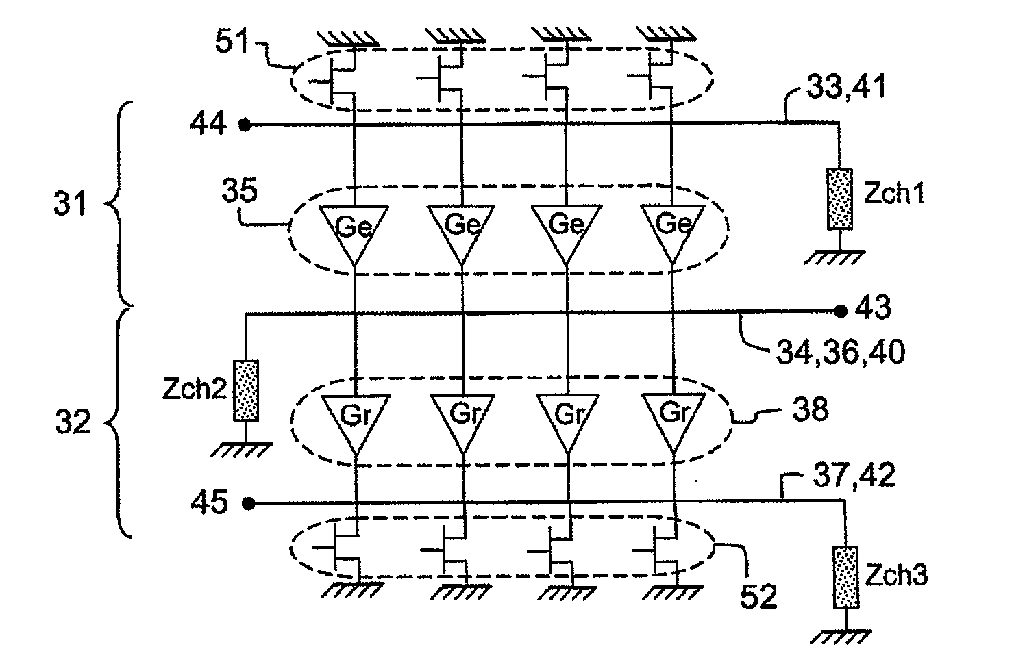
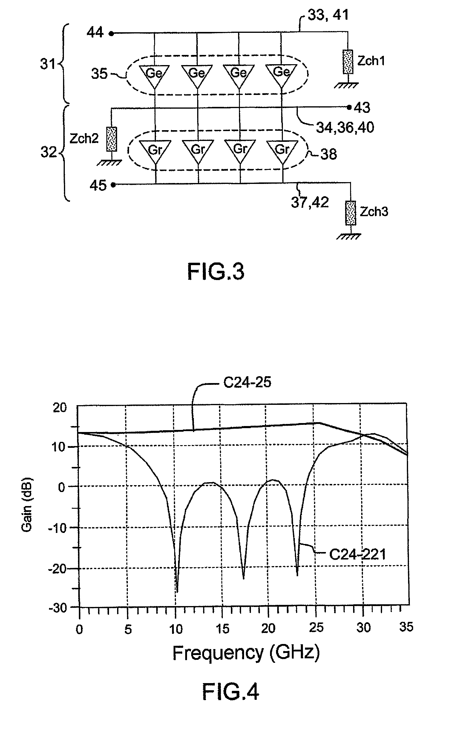
The invention is a controlled RF active duplexer that allows for the splitting of RF signals in a compact space with good isolation between the input and output ports. It includes two distributed amplifiers and means for controlling them. The duplexer is placed in an on state or off state depending on the direction of RF signal flow. The invention also includes a transmission and reception module with the duplexer connected to a transmit pathway, input / output port, and an antenna. The technical effect of the invention is the efficient and reliable splitting of RF signals in a compact space with good isolation between the input and output ports.

Problems solved by technology

Secondly, in receive mode these means must ensure that the signal received travels to the receiver with a minimum of losses, the power of the signal received being generally low, or even very low.
On the other hand, a circulator has significant overall proportions and significant weight, which are penalizing for airborne systems.
Moreover, the bandwidth of a circulator proves to be insufficient for very wide band applications, typically of the order of 3 octaves and more.
However, the main limitation of a passive switch is the absence of directivity between the input and the output of one and the same pathway thereof.
The absence of directivity poses a problem notably when the antenna exhibits a high coefficient of reflection.
A part of the signal to be transmitted is then reflected towards the power amplifier, possibly causing its malfunction or even its destruction.
This separation exhibits an obvious drawback, namely the duplication of a part of the signal processing chain and radiating elements, this being contrary to the philosophy of a transmission and reception module and to the requirement for the integration of electronic devices.

Method used


Image

  • Controlled RF Active Duplexer
  • Controlled RF Active Duplexer
  • Controlled RF Active Duplexer

Examples


Embodiment Construction

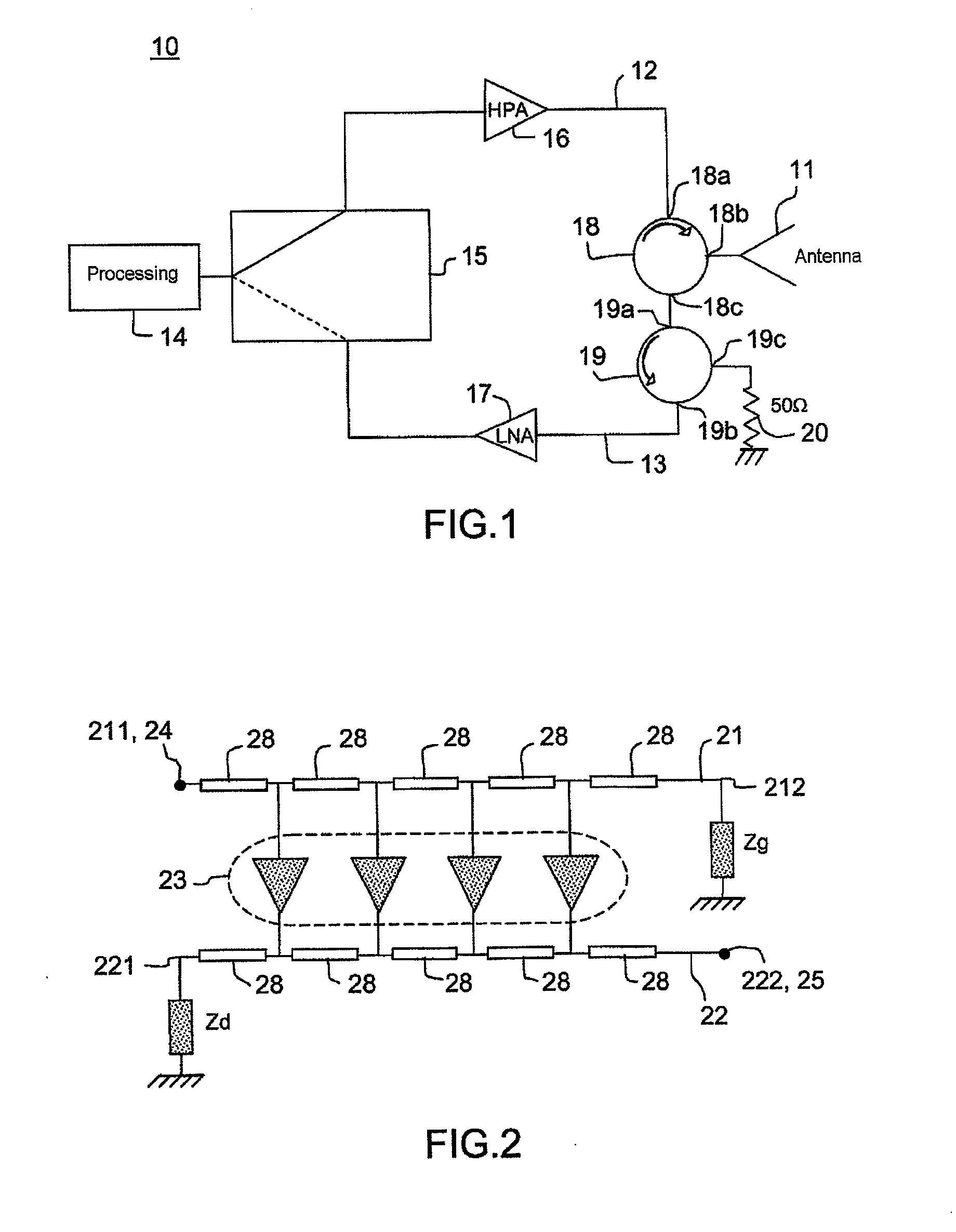
[0019]FIG. 1 illustrates, through a schematic, means 10 making it possible to separate the signals transmitted from the signals received by an antenna 11, these means 10 being able to be installed in a transmission and reception module for a narrowband application. As indicated previously, these means 10 perform on the one hand the splitting of the signals at the foot of the antenna 11 between the transmit pathway 12 and the receive pathway 13 and on the other hand the switching of the processing of the signals according to the operating mode, namely the transmit mode or the receive mode. The transmit pathway 12 and receive pathway 13 are linked to processing means 14 by a switch 15. The switch 15 ensures the linkage between the processing means 14 and one or other of the transmit pathway 12 and receive pathway 13, depending on the operating mode in progress. The transmit pathway 12 generally comprises a power amplifier 16 intended for amplifying the low power signal emanating from ...


PUM


Abstract

A controlled RF active duplexer comprises two distributed amplifiers and means for controlling them. Each distributed amplifier comprises an input line and an output line, the output line of the first distributed amplifier being common to the input line of the second distributed amplifier. An end of the input line of the first distributed amplifier forms the input port, an end of the output line of the second distributed amplifier forms the output port and an end of the line common to the two distributed amplifiers forms the input / output port. The distributed amplifiers are placed in the on state or in the off state in opposition to one another as a function of the ports to be made to communicate. The invention makes it possible to carry out the splitting of the RF signals within a compact space and isolation between input port and output port.

Description

CROSS-REFERENCE TO RELATED APPLICATIONS[0001]This application claims priority of French application no. FR 0804762, filed Aug. 29, 2008, the disclosure of which is hereby incorporated by reference in its entirety.TECHNICAL FIELD[0002]The invention relates to a controlled RF active duplexer. It relates also to a transmission and reception module comprising such an RF active duplexer. The invention applies notably to the field of transmission and reception modules using a single antenna for transmission and reception. It applies more particularly to the field of the transmission and reception modules of airborne systems operating in a wide frequency band.BACKGROUND OF THE INVENTION[0003]Transmission and reception modules using a single antenna for transmission and reception, such as for example the transmission and reception modules with which certain radars are equipped, must comprise means making it possible to separate the signals transmitted from the signals received by the antenn...

Claims


Application Information

Patent Timeline
Patent Type & Authority Applications(United States)
IPC IPC(8): H03H7/46
CPCH03F3/605H04B1/44H03H11/344H03F3/72
Inventor PLAZE, JEAN-PHILIPPEDUEME, PHILIPPEMALLET-GUY, BENOIT
Owner THALES SA
Learn More