
Transponder Comprising an Electronic Memory Chip and Magnetic Circular Antenna

a technology of magnetic circular antenna and electronic memory chip, which is applied in the direction of loop antenna, radiating element structure, instruments, etc., can solve the problems of affecting the marking of small objects of known transponder systems, and affecting the detection accuracy of barcodes

Inactive Publication Date: 2010-03-04
DYNAMIC SYST INC
View PDF20 Cites 55 Cited by
  • Summary
  • Abstract
  • Description
  • Claims
  • Application Information

AI Technical Summary

Benefits of technology

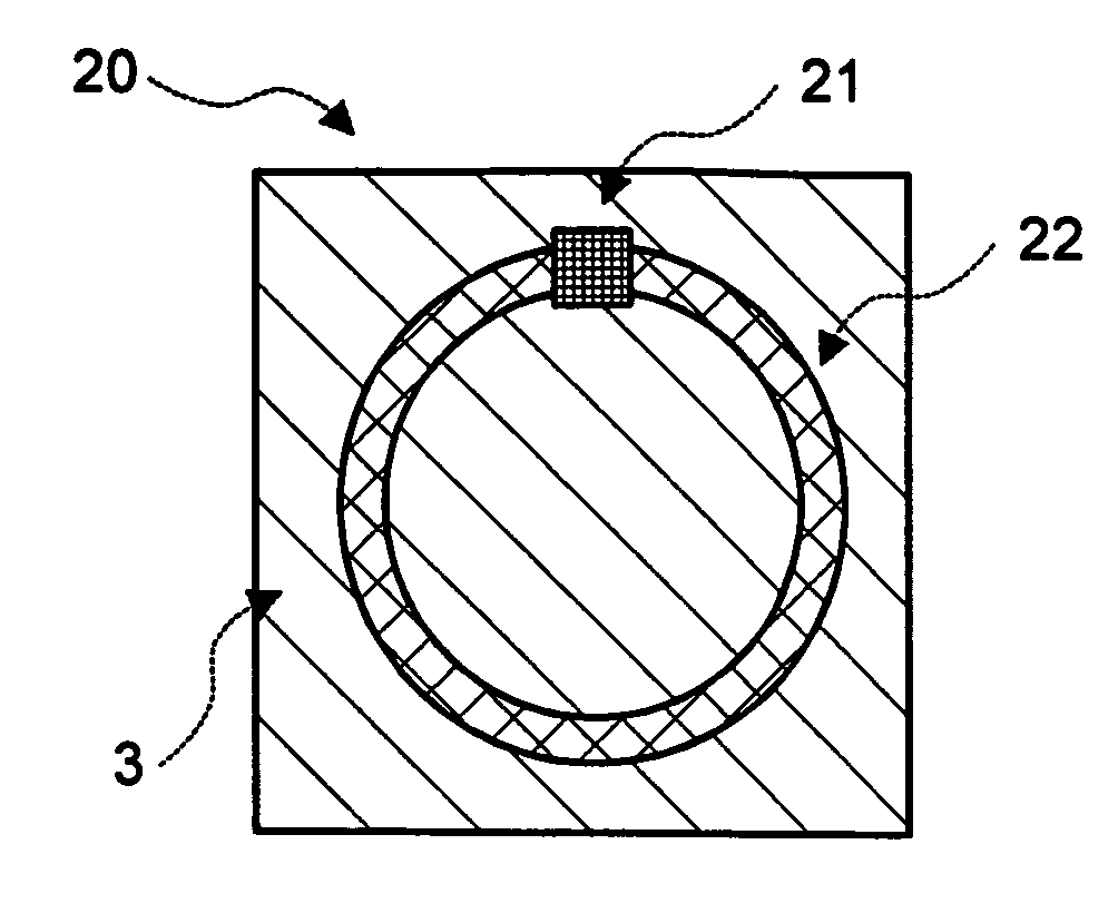
[0014]This is where the present invention begins. The object of the present invention, as characterized in the claims, is to avoid the disadvantages of the background art and especially to specify a generic transponder that exhibits a good read range also in small designs and, furthermore, can be produced economically.
[0022]In both aspects of the present invention, especially the following advantages are realized, as stated in greater detail below:
[0026]simple possibility of tuning after manufacturing a semifinished transponder product;
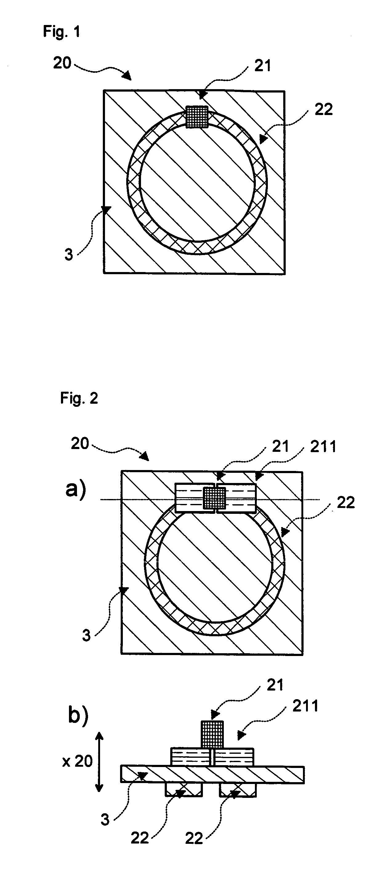
[0037]The variant of the present invention having an additional secondary antenna permits, through the combination of two different components, a particularly efficient and flexible manufacture: For one thing, the transponder includes a more complex, but small and standardized component, namely the transponder chip on a magnetic ring antenna having a typical diameter of only about 1 cm, for which higher standards are set for the production precision. The reception characteristic of this transponder is improved through the combination of the ring antenna, which is particularly well suited in the magnetic near field, with a secondary antenna that is generally more easily manufacturable, substantially larger, and particularly suited for the electromagnetic far field.
[0045]The number of turns of the coil is preferably less than 20, preferably less than 10, and is especially 1, 2 or 3. Here, the number of turns 1 brings the additional advantage that no bridge is required to join the coil ends.
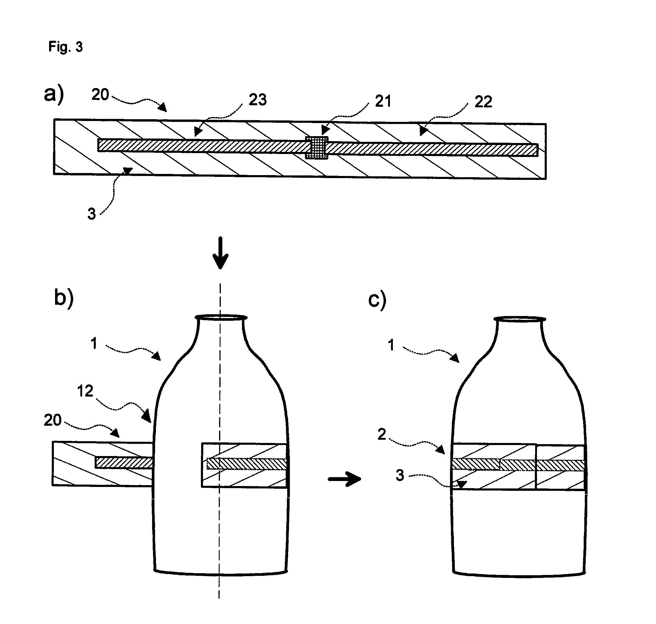
[0056]According to a further embodiment of the present invention, the semifinished transponder product is advantageously formed such that, when rolling up, independently of the chosen circumference, within a permitted range, the resonance frequency of the transponder does not change significantly. Here, the circuit paths are preferably formed such that the size of the overlapping portion decreases with increasing circumference in such a way that the attendant increasing inductance of the antenna is compensated for by a decreasing capacity.

Problems solved by technology

Here, the transponder, or RFID, technology proves to be more robust than conventional marking systems, especially labels having barcodes: Despite a growing number of built-in redundancies, the chances of detecting dirty, covered or damaged barcodes are poor.
To create the conductive connection, methods such as conductive adhesion, bonding (welding) or crimping are used that each incur additional costs.
The known transponder systems encounter technical limits in marking small objects: Small designs are possible in inductively coupled systems, but the inductance and the read range decrease with shrinking cross-sectional areas of the ring antenna.
Due to the small inductance, a large capacity is required for the common transponder frequencies of inductive systems, which is typically reflected in higher costs.

Method used


Image

  • Transponder Comprising an Electronic Memory Chip and Magnetic Circular Antenna
  • Transponder Comprising an Electronic Memory Chip and Magnetic Circular Antenna
  • Transponder Comprising an Electronic Memory Chip and Magnetic Circular Antenna

Examples


Embodiment Construction

[0014]This is where the present invention begins. The object of the present invention, as characterized in the claims, is to avoid the disadvantages of the background art and especially to specify a generic transponder that exhibits a good read range also in small designs and, furthermore, can be produced economically.

[0015]According to the present invention, this object is solved by the transponder having the features of the independent claims. Further advantageous details, aspects and embodiments of the present invention are evident from the dependent claims, the description, the drawings and the examples.

[0016]The following abbreviations and terms will be used in the context of the present invention:

[0017]The abbreviation RFID (radio frequency identification) is used here generally for identification systems with contactless electromagnetic energy and data transmission—independently of the carrier frequency used.

[0018]A transponder readout device is understood to be a system that...


PUM


Abstract

In a transponder having an electronic memory chip and a magnetic ring antenna is provided that the ring antenna comprises an electrically conductive coil having at least one turn, and a capacitor, wherein the capacitor exhibits, as a dielectric, a thin insulator foil that simultaneously serves as a substrate foil for the coil and / or the chip.

Description

FIELD OF THE INVENTION[0001]The present invention relates to a transponder having an electronic memory chip and a magnetic ring antenna. The present invention further relates to a semifinished transponder product and a manufacturing method for such a transponder.BACKGROUND OF THE INVENTION[0002]Transponder technology has been used successfully for years in many applications: Typical examples are the contactless company ID that enables entrance to the workplace, and the immobilizer system based on a transponder built into the vehicle key. Here, the transponder, or RFID, technology proves to be more robust than conventional marking systems, especially labels having barcodes: Despite a growing number of built-in redundancies, the chances of detecting dirty, covered or damaged barcodes are poor. RFID technology, on the other hand, which is not dependent on an optical line of sight, offers a constantly high reading quality also with heavily soiled data carriers. Further advantages of RFI...

Claims


Application Information

Patent Timeline
Patent Type & Authority Applications(United States)
IPC IPC(8): H04Q5/22H01Q1/00
CPCG06K19/07749G06K19/0776H01Q7/00H01Q1/2208H01Q1/38G06K19/07786
Inventor LOSSAU, HARALD
Owner DYNAMIC SYST INC
Learn More