Magnetic antenna and antenna device

Active Publication Date: 2010-03-04
MURATA MFG CO LTD
View PDF3 Cites 27 Cited by
  • Summary
  • Abstract
  • Description
  • Claims
  • Application Information

AI Technical Summary

Benefits of technology

[0008]In view of the above, preferred embodiments of the present invention provide a highly sensitive magnetic antenna and an antenna device having strong coupling wit

Problems solved by technology

Hence, magnetic flux coming from a direction substantially perpendicular to the main surfaces of the magnetic core is not able to pass through the

Method used


Image

  • Magnetic antenna and antenna device
  • Magnetic antenna and antenna device
  • Magnetic antenna and antenna device

Examples


first preferred embodiment

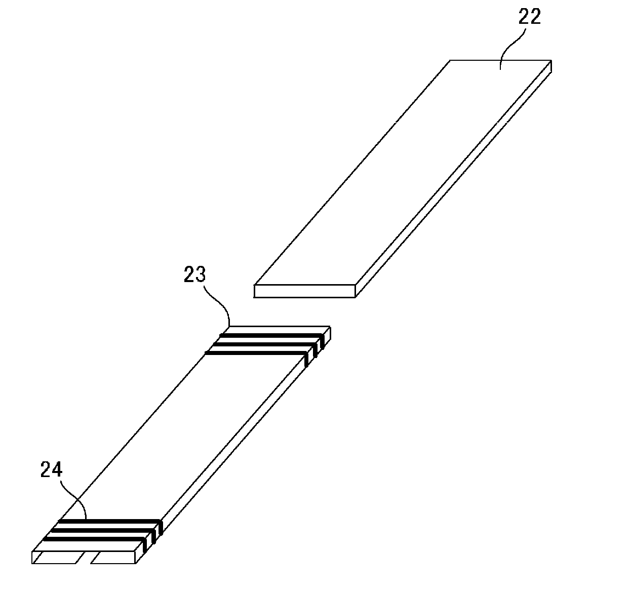
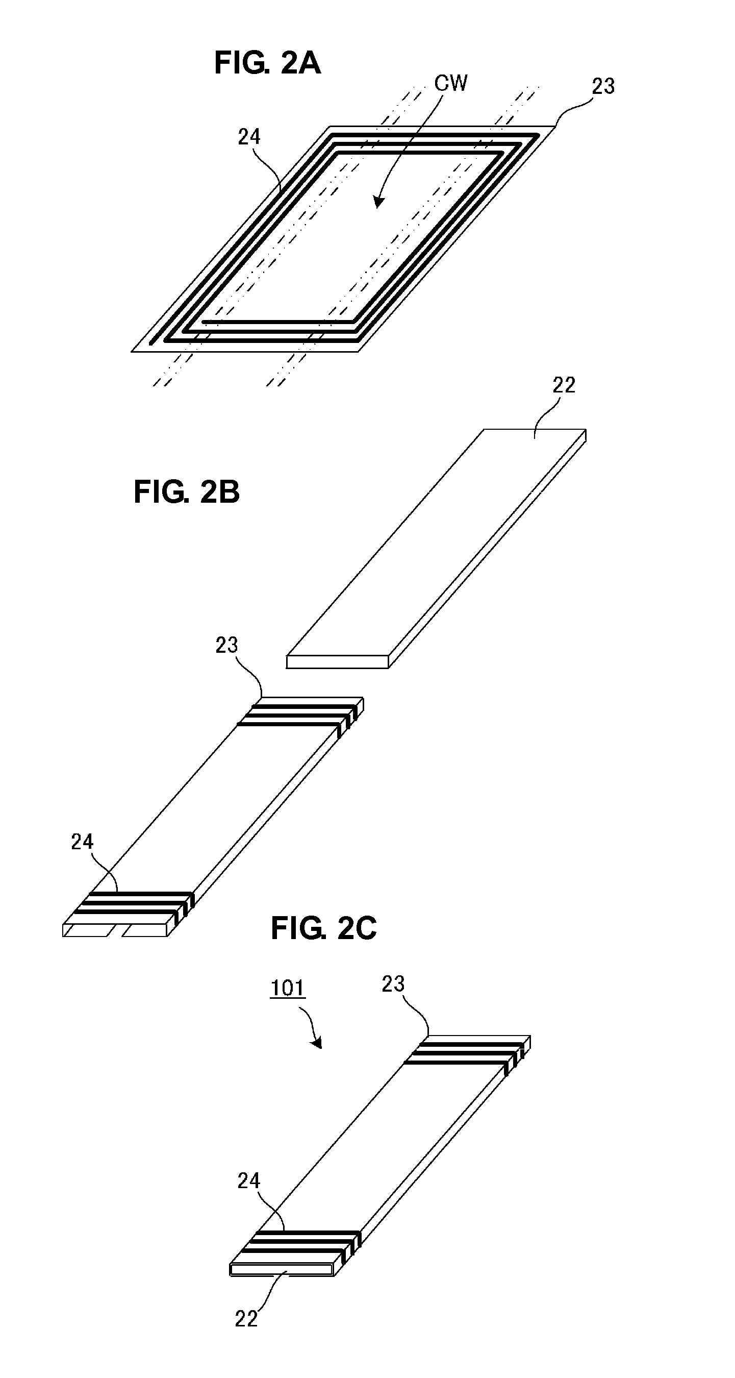
[0026]FIGS. 2A to 2C show a structure of a magnetic antenna 101 according to a first preferred embodiment of the present invention. FIG. 2A shows a perspective view of a flexible substrate, in a developed state, used in the magnetic antenna 101. FIG. 2B shows a perspective view of a magnetic core and the flexible substrate, in a folded state, used in the magnetic antenna 101. FIG. 2C shows a perspective view of the magnetic antenna 101.

[0027]Referring to FIGS. 2A to 2C, the magnetic antenna 101 includes a flexible substrate 23 having a coil conductor 24 provided thereon, and a magnetic core 22. On the flexible substrate 23, the coil conductor 24 preferably has a substantially rectangular spiral shape, where the center portion of the winding of the coil conductor 24 is formed as a conductor opening CW. In other words, the substantially-spiral-shaped coil conductor 24 is arranged so as to surround the conductor opening CW.

[0028]Referring to FIG. 2A, the four two-dot chain lines denote...

second preferred embodiment

[0032]FIGS. 3A and 3B show a structure of a magnetic antenna 101 and an antenna device 201 according to a second preferred embodiment of the present invention. FIG. 3A shows a perspective view of the antenna device 201 and FIG. 3B illustrates a current that flows in the coil conductor of the magnetic antenna 101 and magnetic flux that passes through a magnetic core.

[0033]Referring to FIG. 3A, the antenna device 201 is configured by mounting the magnetic antenna 101 on a metal plate 31. The metal plate 31 is, for example, a conductor (ground pattern) disposed on a circuit substrate. The metal plate 31 corresponds to a “plate member having a sheet-shaped conductor” according to a preferred embodiment of the present invention.

[0034]Referring to FIG. 3A, the dotted lines represent major magnetic paths. By providing the magnetic antenna 101 on the metal plate 31 that does not allow passage of magnetic flux therethrough, magnetic paths are provided along which magnetic flux MFa substantia...

third preferred embodiment

[0041]FIGS. 5A to 5C show a structure of a magnetic antenna 102 according to a third preferred embodiment of the present preferred embodiment. FIG. 5A shows a developed view of a flexible substrate used in the magnetic antenna 102. FIG. 5B shows a perspective view of a magnetic core 22 used in the magnetic antenna 102. FIG. 5C shows a perspective view of the magnetic antenna 102.

[0042]In the magnetic antenna 102 according to the third preferred embodiment, two coil conductors 24a and 24b each shaped like a substantially rectangular spiral are provided on the flexible substrate 23. The two coil conductors 24a and 24b have opposite winding directions and are serially connected to each other on the flexible substrate 23. The two coil conductors 24a and 24b have respective connection portions 25a and 25b of the coil conductors provided at the respective inner ends thereof.

[0043]The four two-dot chain lines shown in FIG. 5A denote lines along which the flexible substrate 23 is to be bent...


PUM


Abstract

A highly sensitive magnetic antenna and an antenna device achieve strong coupling with magnetic flux substantially perpendicular to main surfaces of a magnetic core, an enlarged antenna opening, and increased efficiency of magnetic flux radiation. The magnetic antenna includes a flexible substrate and a magnetic core preferably having a substantially rectangular plate shape. The flexible substrate has a spiral coil conductor located thereon, and the coil conductor has a conductor opening located at the center of the winding center thereof. The flexible substrate is bent in the vicinity of the two sides of the coil conductor spaced apart from the center of the conductor opening and along the two sides of the magnetic core, so as to wrap around the upper surface, left and right surfaces, and portions of the lower surface of the magnetic core.

Description

BACKGROUND OF THE INVENTION[0001]1. Field of the Invention[0002]The present invention relates to a magnetic antenna and an antenna device for use in, for example, a radio frequency identification (RFID) system that communicates with external apparatuses via an electromagnetic signal.[0003]2. Description of the Related Art[0004]In RFID systems, which have been increasingly used in recent years, data communication is performed between a mobile electronic apparatus, such as a cellular phone, and a reader / writer each provided with an antenna for information communication. Regarding the antenna provided in a mobile electronic apparatus, in particular, there is strong demand for increased performance and reduced price and size. In response to this demand, a magnetic antenna having a magnetic core disclosed in Japanese Patent No. 3772778 has been developed.[0005]FIG. 1 is a perspective view of the magnetic antenna shown in Japanese Patent No. 3772778. An antenna 10 includes a magnetic core...

Claims


Application Information

Patent Timeline
IPC IPC(8): H01Q1/36
CPCH01Q1/20H01Q7/00H01Q1/38H01Q1/2208
Inventor YOSUI, KUNIAKIKUBO, HIROYUKIITO, HIROMITSU
Owner MURATA MFG CO LTD
Why Eureka
Try Eureka