Unlock instant, AI-driven research and patent intelligence for your innovation.

Liquid crystal display

Active Publication Date: 2010-03-04
MAXELL HLDG LTD
View PDF2 Cites 9 Cited by
  • Summary
  • Abstract
  • Description
  • Claims
  • Application Information

AI Technical Summary

Benefits of technology

[0008]The side-edge-type backlight has a bar-shaped light source, such as a cold cathode fluorescent lamp, installed on a side of a light guide plate. The light emitted from the bar-shaped light source is incident on the side of the light guide plate and guided by the light guide plate and a reflecting sheet in closely contact with the lower surface of the light guide plate to provide uniform light that illuminates the liquid crystal panel disposed over the light guide plate.
[0009]According to the patent documents described above, measures are taken to prevent light leakage that occurs because of the structure of the backlight. However, since the light source is a bar-shaped light source, such as a cold cathode fluorescent light, the area of the rim part of the liquid crystal panel, which is not the effective pixel area, is large, the power consumption is high, and the weight is heavy.
[0010]In view of the problems described above, an object of the present invention is to provide a liquid crystal display that has a narrower rim part, a higher light emission efficiency and a lower power consumption than conventional products.
[0017]According to the present invention, since an LED light source is used for backlight, the power consumption is low, and the life is long. In addition, since the backlight is the side-edge type, the thickness of the liquid crystal display can be reduced. In addition, according to the present invention, the width of the rim can be reduced. In addition, the light emission efficiency can be improved. In addition, the number of components can be reduced.

Problems solved by technology

However, since the light source is a bar-shaped light source, such as a cold cathode fluorescent light, the area of the rim part of the liquid crystal panel, which is not the effective pixel area, is large, the power consumption is high, and the weight is heavy.

Method used


Image

  • Liquid crystal display
  • Liquid crystal display
  • Liquid crystal display

Examples


Embodiment Construction

[0026]In the following, an embodiment of the present invention will be described in detail with reference to the accompanying drawings. Note that, through the drawings, components having the same functions are denoted by the same reference numerals, and redundant descriptions will be omitted as far as possible.

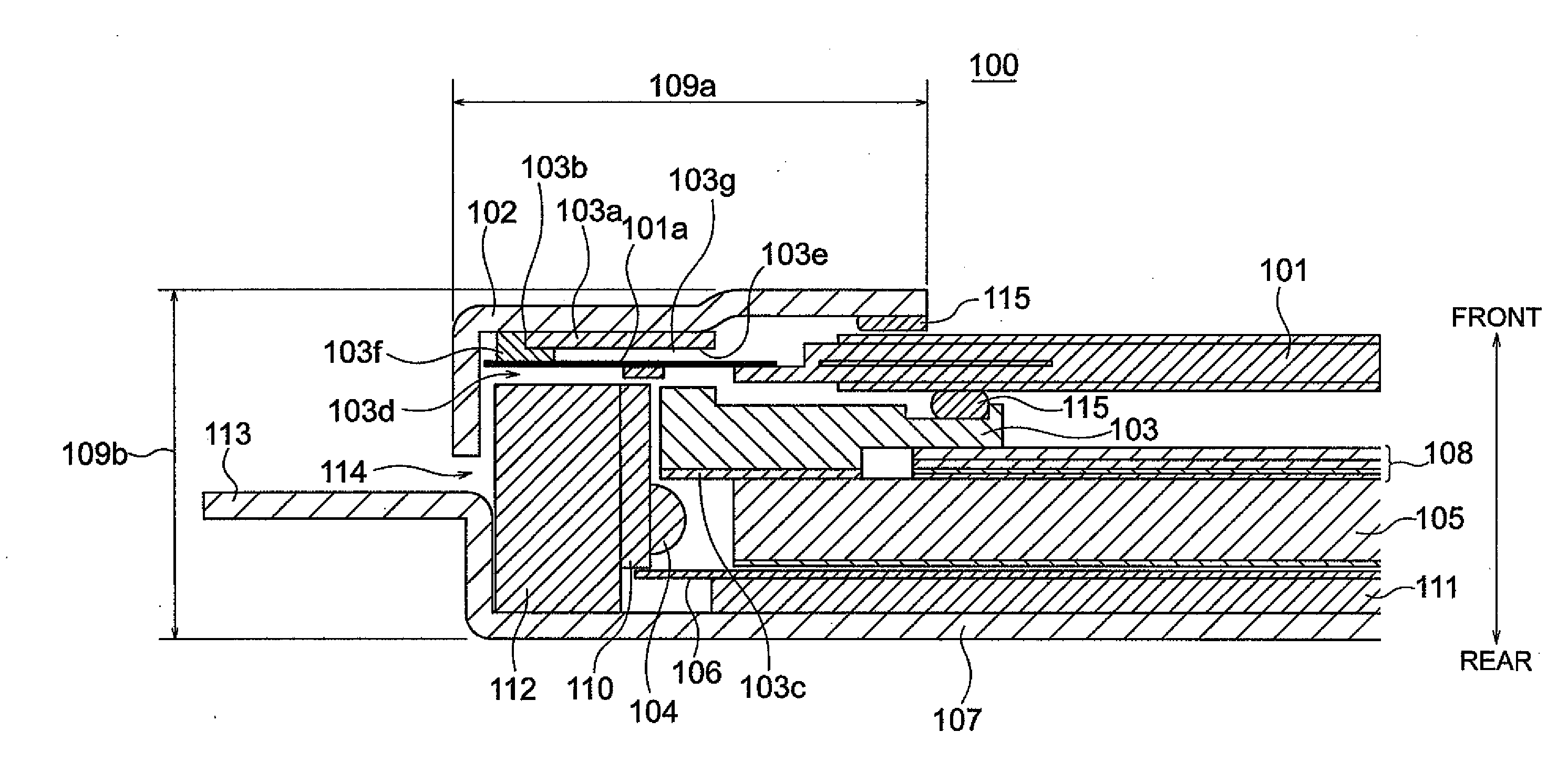
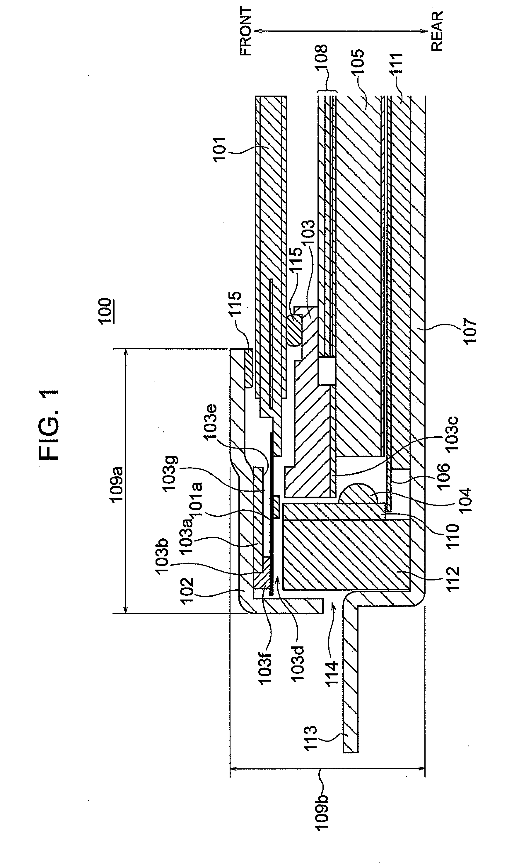
[0027]FIG. 1 is a partially cross-sectional view showing a liquid crystal display according to an embodiment of the present invention. Reference numeral 100 denotes a liquid crystal display according to the present invention, reference numeral 101 denotes a liquid crystal panel, reference numeral 101a denotes a gate chip on film (COF), reference numeral 104 denotes a light emitting diode (LED) serving as a light source, reference numeral 102 denotes a front cover, reference numeral 103 denotes a frame, reference numeral 103a denotes a lid, reference numeral 103b denotes a hinge, reference numeral 103c denotes a reflecting surface that is disposed on the rear surface of the fra...


PUM


Abstract

A liquid crystal display has a liquid crystal panel, a gate chip on film (COF) disposed at a side of a side surface of the liquid crystal panel, side-edge-type backlights having a light emitting diode disposed on left and right side surfaces of the liquid crystal panel, and a cover and a frame that hold the liquid crystal panel and the backlights, the frame has an opening disposed at a position corresponding to the position of the gate COF into which the gate COF is inserted, and a lid for covering the gate COF inserted in the opening is connected to the frame in such a manner that the lid is capable of being opened and closed.

Description

INCORPORATION BY REFERENCE[0001]The present application claims priority from Japanese application JP2008-226679 filed on Sep. 4, 2008, the content of which is hereby incorporated by reference into this application.BACKGROUND OF THE INVENTION[0002](1) Field of the Invention[0003]The present invention relates to a liquid crystal display, for example. In particular, it relates to a side-edge type liquid crystal display that incorporates a light emitting diode.[0004](2) Description of Related Art[0005]In recent years, television broadcast has been digitalized and improved in definition, and thus, there is a demand for a flat-screen image display with a larger size (larger screen) as a television receiver. As the large-size flat-screen image display, in addition to the conventional projection display, liquid crystal displays (LCDs) using a flat panel display (FPD), such as a plasma display panel (PDP) and an organic electro-luminescence (OEL) panel, have appeared on the market.[0006]Of t...

Claims


Application Information

Patent Timeline
IPC IPC(8): G09G3/36
CPCG02F1/133308G02F1/133615G02F2001/133328G02F2001/133325G02F2001/133317G02F1/133317G02F1/133325G02F1/133328
Inventor SATO, KATSUNARIYAMASHITA, YOSHIHARUMIITSU, TAKESHIOGURA, HIROYOSHIHOSONO, HIROKISATO, KOICHI
Owner MAXELL HLDG LTD