Filter device, image correction circuit, image dispay device, and method of correcting image

a filter device and image technology, applied in image enhancement, color signal processing circuits, instruments, etc., can solve problems such as unnatural image display, unnatural image quality, and unnatural display, and achieve the effect of suppressing an unnatural variation in image quality

Inactive Publication Date: 2010-03-04
SONY CORP
View PDF2 Cites 22 Cited by
  • Summary
  • Abstract
  • Description
  • Claims
  • Application Information

AI Technical Summary

Benefits of technology

[0017]In the filter device, the image correction circuit, the image display device, and the method of correcting the image according to the embodiment of the present invention, a filtering operation is performed on the input image data so that, when time-varying amount in a total frequency value in a neighboring-classes block configured with a couple of neighboring classes in the histogram distribution of the image data is equal to or less than a predetermined value, time-varying amount of a frequency value in each of the classes in the neighboring-classes block is suppressed to be equal to or less than a predetermined limitation value. Thereby, even when a variation amount of the frequency value is large between the distribution levels in the neighboring-classes block, the variation becomes gradual. Therefore, at the time of performing the image processing for image data through use of the histogram distribution after such a filtering operation, it is possible to suppress an unnatural variation in image quality which is caused by image processing.

Problems solved by technology

However, in such a method, in the case where the frequency in the histogram distribution is concentrated to a vicinity of a boundary between a couple of luminance level classes immediately adjacent to each other, for example, as indicated with arrows in FIG. 15, when a DC variation is generated, there is a possibility that an issue occurs as will be described below.
In such a large image variation, a sense of unnaturalness in the display quality is caused, and an image is unnaturally displayed.
Such an issue is particularly obvious in the case where the number of divisions in the luminance level is small.

Method used


Image

  • Filter device, image correction circuit, image dispay device, and method of correcting image
  • Filter device, image correction circuit, image dispay device, and method of correcting image
  • Filter device, image correction circuit, image dispay device, and method of correcting image

Examples


Embodiment Construction

[0035]A preferred embodiment of the present invention will be described in detail with reference to the accompanying drawings.

Configuration Example of a Whole Image Display Device

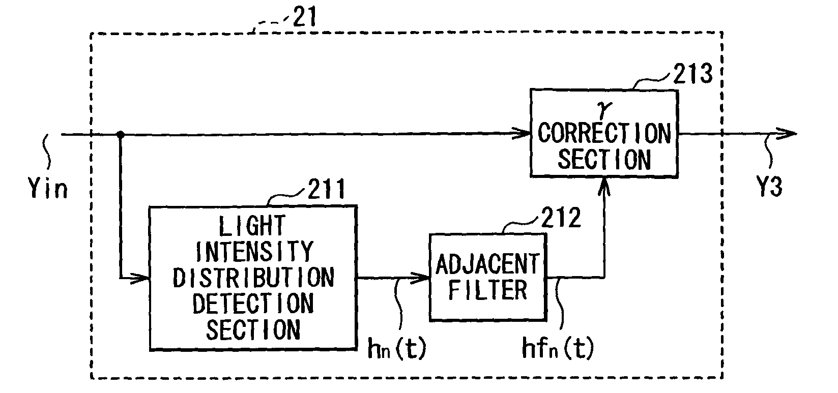
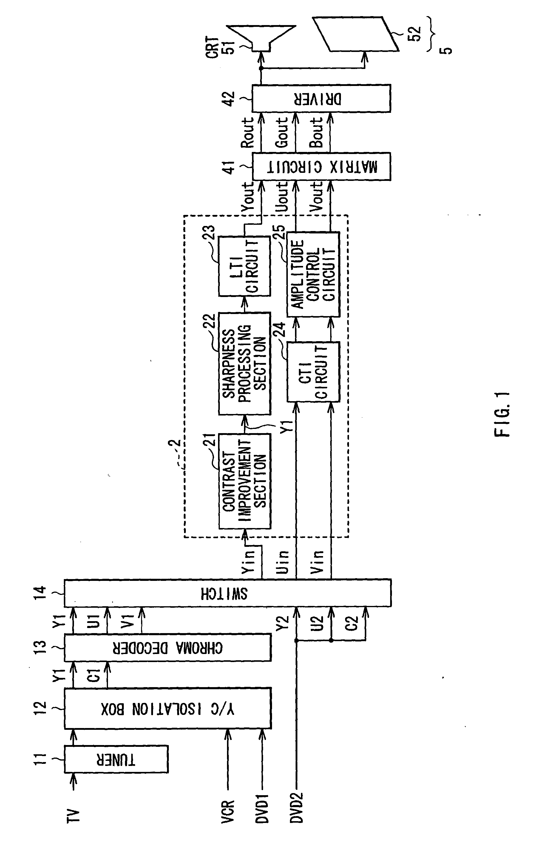
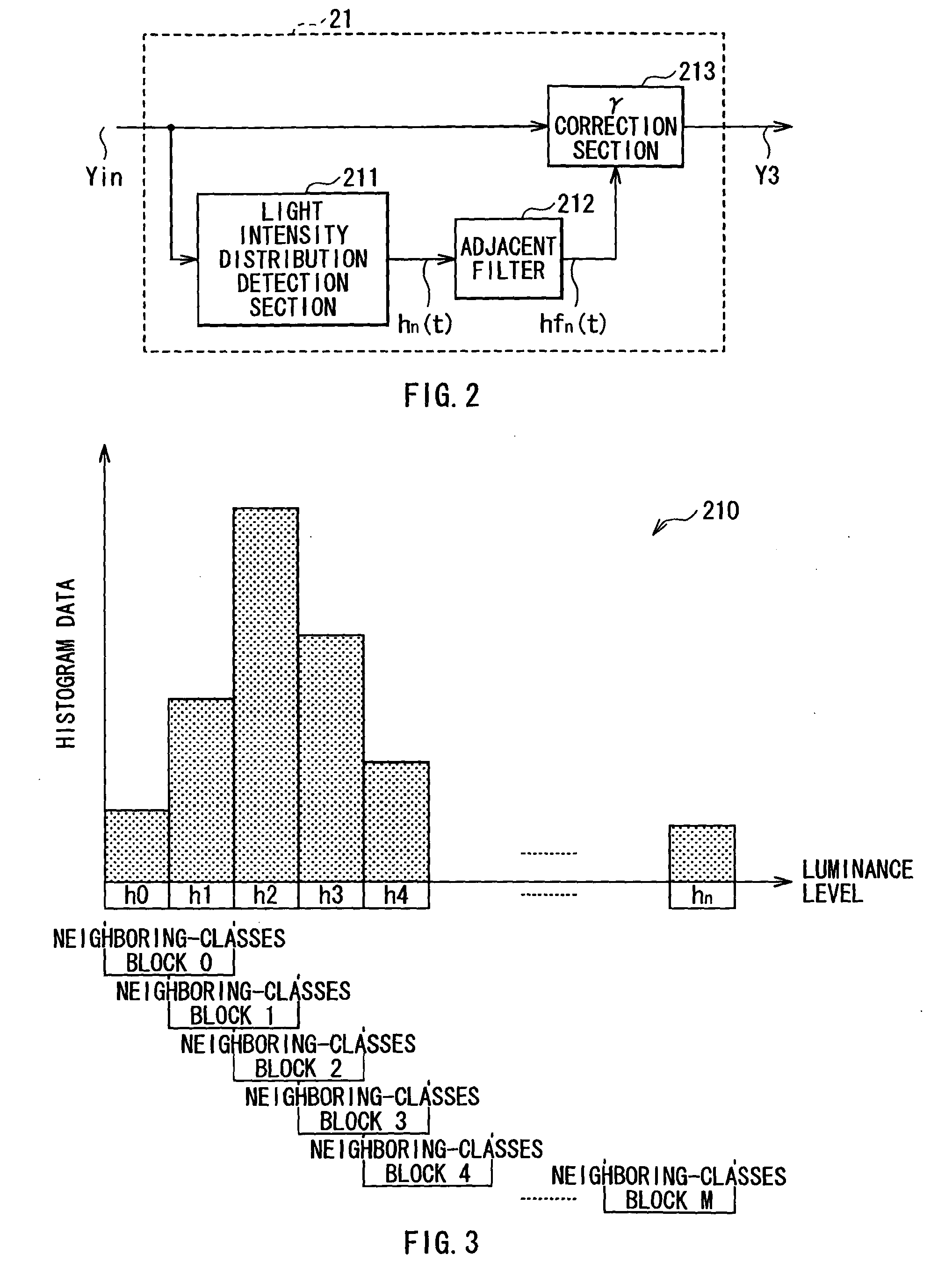
[0036]FIG. 1 indicates the overall configuration of an image display device according to an embodiment of the present invention. The image display device includes a tuner 11, a Y / C isolation circuit 12, a chroma decoder 13, a switch 14, an image processing section 2, a matrix circuit 41, a driver 42, and a display 5. Since a method of correcting an image according to an embodiment of the present invention is realized in the image display device according to the embodiment, the method of correcting an image will be also described below.

[0037]An image signal input to this image display device may be a television signal from a TV (television). In addition to this, the image signal may be an output from a VCR (video cassette recorder), a DVD (digital versatile disc), or the like. In this manner, image informati...


PUM


Abstract

The present invention provides a filter device allowing unnatural variation in image quality caused by image processing to be suppressed. The filter device including a filter section performing a filtering operation on an input image data so that, when time-varying amount in a total frequency value in a neighboring-classes block configured with a couple of neighboring classes in a histogram distribution of the input image data is equal to or less than a predetermined value, time-varying amount of a frequency value in each of the classes in the neighboring-classes block is suppressed to be equal to or less than a predetermined limitation value.

Description

CROSS-REFERENCE TO RELATED APPLICATION[0001]The present application claims priority from Japanese Patent Application No. JP 2008-225123 filed in the Japanese Patent Office on Sep. 2, 2008, the entire content of which is incorporated herein by reference.BACKGROUND OF THE INVENTION[0002]1. Field of the Invention[0003]The present invention relates to an image correction circuit performing image correction to image data, and a method of correcting an image, a filter device used when such an image correction is performed, and an image display device including such an image correction circuit.[0004]2. Description of the Related Art[0005]In general, a device such as a television receiver, a VTR (video tape recorder), a digital camera, a television camera, or a printer has an image processing function in which an image is output after being subjected to image quality correction (for example, functions such as adjustment in light-dark and contrast, and correction of outline). Mainly, such fu...

Claims


Application Information

Patent Timeline
Patent Type & Authority Applications(United States)
IPC IPC(8): G09G5/02G06K9/40G06T5/00G06T5/20G06T5/40H04N1/407H04N5/14H04N5/208H04N9/68
CPCG06T5/009G06T5/40H04N21/44H04N5/57H04N5/202
Inventor HARADA, SHIGERUYAMAGUCHI, MUNEHISA
Owner SONY CORP
Why Eureka
Try Eureka