
Liquid crystal lens with variable focus

a liquid crystal lens and variable focus technology, applied in non-linear optics, instruments, optics, etc., can solve the problems of long response time, slow switching speed, and inability to control precision, so as to reduce the problem of aperture decentering, improve the switch speed of focus, and facilitate adjustment

Inactive Publication Date: 2010-03-04
E PIN OPTICAL IND
View PDF7 Cites 34 Cited by
  • Summary
  • Abstract
  • Description
  • Claims
  • Application Information

AI Technical Summary

Benefits of technology

"The present invention provides a liquid crystal lens with variable focus. The lens includes at least two glass substrates with surface electrode patterns made of metal membrane or transparent conductive membrane. The lens can change focus by applying voltage to the surface electrode patterns to adjust the arrangement of liquid crystal molecules. The lens can be used in cameras, phone cameras, or 3D image processing devices for change of focus. The invention also provides a single-layer or multi-layer liquid crystal lens with variable focus, a surface electrode pattern designed as a single hole pattern or concentric circle pattern for changing various optical properties such as aperture, refractive index, and focal length, and easy adjustment of surface electrode patterns to reduce decentered problems of the aperture of the lens. The invention also reduces the thickness of the whole lens and manufacturing cost."

Problems solved by technology

Thus such structure has difficulties in design, control precision and the manufacturing cost is also quite high.
However, the transparent conductive ITO membrane requires higher voltage so that ITO membrane has shortcomings of long response time and slow switching speed while being applied to the liquid crystal lens module.
Therefore, such module is not suitable for cameras or phone cameras.
However, there is an edge attenuation that leads to poor image quality.
Moreover, there are still some other problems such as high operation voltage, low focusing efficiency, dependence between the focusing efficiency and polarization, and narrow variable focus range.
Thus there are quite a lot restrictions on the use.
But the whole thickness and the cost of the lens are also increase.
And the switching speed of the focus is still a problem, not enhanced efficiency.

Method used


Image

  • Liquid crystal lens with variable focus
  • Liquid crystal lens with variable focus
  • Liquid crystal lens with variable focus

Examples


first embodiment

The First Embodiment

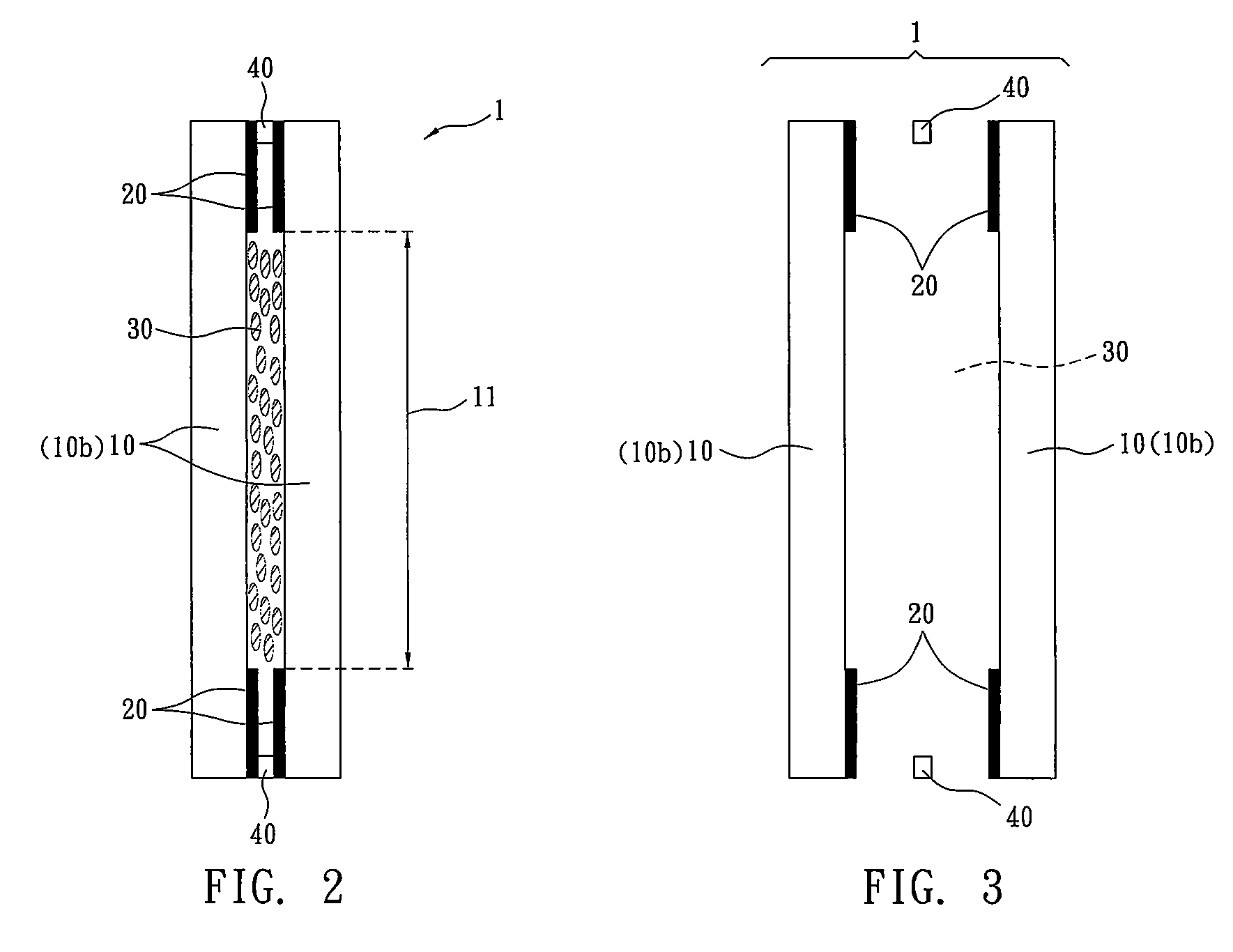
[0028]Refer to FIG. 2&FIG. 3, a single-layer liquid crystal lens with variable focus 1 of the present invention comprising: in the order from an object side to an image side, a single-side electrode glass substrate 10b (a glass substrate 10 disposed with a surface electrode pattern 20 on one side), a spacer 40, a liquid crystal layer 30 and a single-side electrode glass substrate 10b. Wherein, the surface electrode pattern 20 is a metal membrane such as aluminum, silver or gold membrane coated on the glass substrate 10 and the metal membrane is transparent, aluminum surface electrode pattern is used in this embodiment. Wherein, the surface electrode pattern 20 is a single hole pattern, the membrane is etched to form a single-hole aperture 11. Wherein, the spacer 40 can be a circular piece or overlapped circular pieces. The distance of a gap between the two glass substrates 10 is defined by the spacer 40 and this is also the thickness of the liquid crystal layer 3...

second embodiment

The Second Embodiment

[0038]Refer to FIG. 9, a double-layer liquid crystal lens with variable focus 2 of the present invention comprising: in the order from an object side to an image side, a single-side electrode glass substrate 10b, a spacer 40, a first liquid crystal layer 30, a double-side electrode glass substrate 10a, a spacer 40, a second liquid crystal layer 30 and a single-side electrode glass substrate 10b. Wherein, the spacers 40 are arranged among the two single-side electrode glass substrates 10b and the double-side electrode glass substrate 10a to define the two liquid crystal layers 30. The incident light passes the first liquid crystal layer 30 and the second liquid crystal layer 30, being reflected twice. Wherein, the metal membrane of the surface electrode pattern 20 is made from silver in this embodiment. When voltage is applied to the first liquid crystal layer 30 as well as the second liquid crystal layer 30 respectively and the reflective index n1 and n2 are gen...

third embodiment

The Third Embodiment

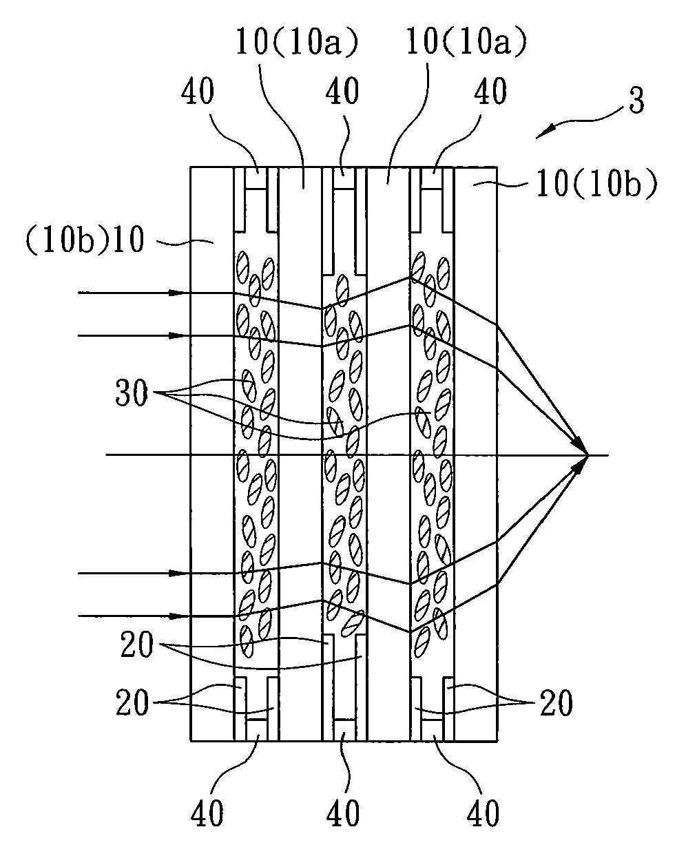
[0043]Refer to FIG. 10, a multiple-layer liquid crystal lens with variable focus 3 of the present invention, in FIG. 10 is shown a triple-layer liquid crystal lens, comprising of a single-side electrode glass substrate 10b, a spacer 40, a first liquid crystal layer 30, a double-side electrode glass substrate 10a, a spacer 40, a second liquid crystal layer 30, a double-side electrode glass substrate 10a, a spacer 40, a third liquid crystal layer 30, and a single-side electrode glass substrate 10b from the object side to the image side. The spacers 40 are arranged among the two single-side electrode glass substrates 10b on outer side and the two double-side electrode glass substrates 10a on inner side to define the three liquid crystal layers 30. The incident light passes the first liquid crystal layer 30, the second liquid crystal layer 30, and the third liquid crystal layer 30, being reflected three times. When voltage is applied to the first liquid crystal layer...


PUM

PropertyMeasurementUnit
thicknessaaaaaaaaaa
transparentaaaaaaaaaa
voltageaaaaaaaaaa

Abstract

A liquid crystal lens with variable focus formed by a single layer or multiple layers of liquid crystal lens unit is revealed. The liquid crystal lens unit includes two glass substrates with preset thickness and arranged in parallel so as to form a middle space for accommodation of liquid crystal layer. By etching, an aluminum membrane, silver membrane or other transparent metal membranes to form surface electrode patterns that can be controlled independently. The arrangement and the refractive index of each liquid crystal layer can be tuned by adjustment of the applied voltage so as to improve image quality, increase focus switch speed, improve easiness of assembling, reduce whole thickness of the lens, and the manufacturing cost.

Description

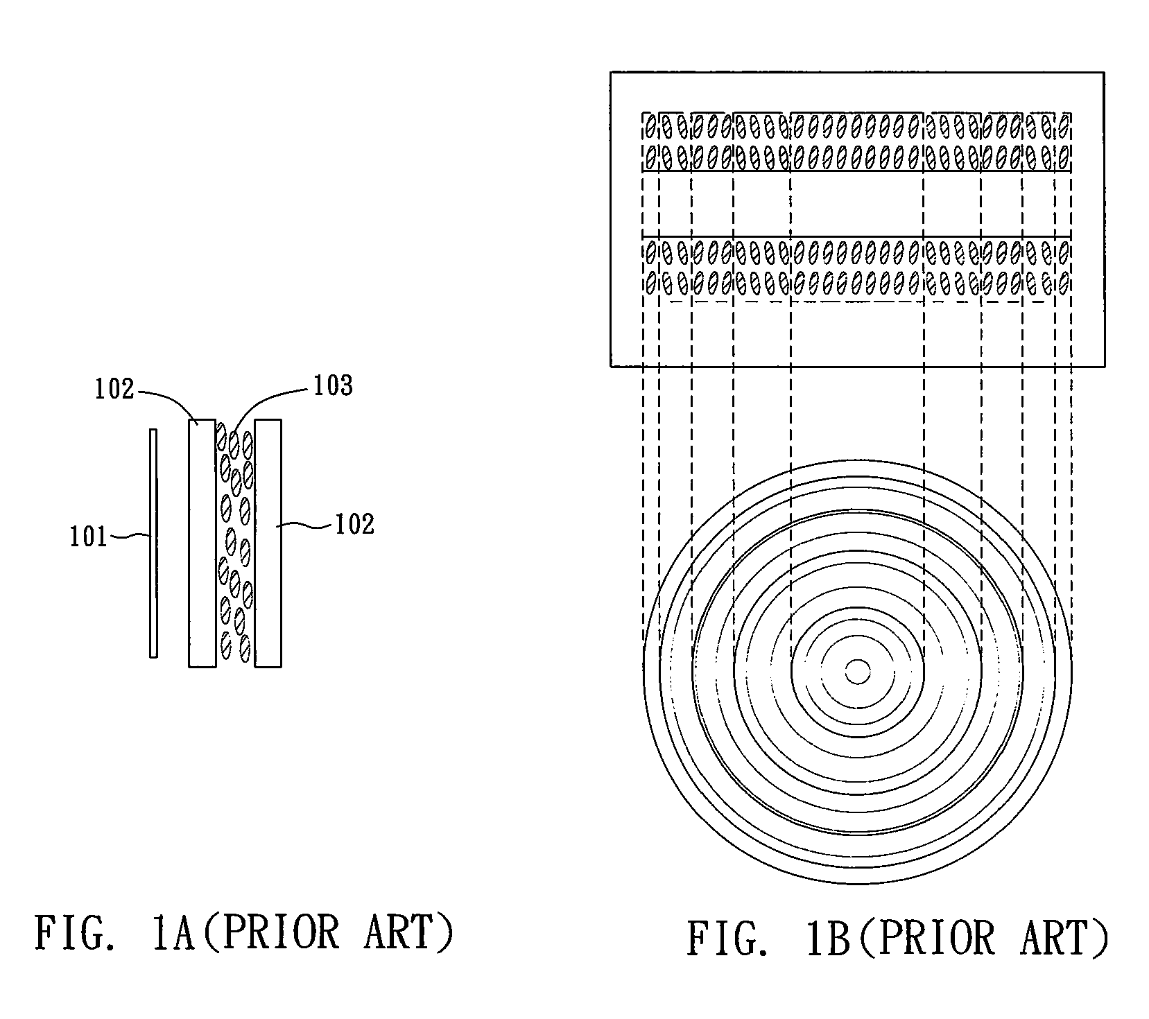
BACKGROUND OF THE INVENTION[0001]The present invention relates to a liquid crystal lens with variable focus, especially to a glass substrate with surface electrode pattern formed by transparent metal membrane for independently tuning optical properties of each liquid crystal lens unit. The liquid crystal lens is applied to cameras, phone cameras or 3D image processing devices and so on.[0002]Generally cameras, phone cameras or 3D image processing devices are disposed with varifocal lenses for magnifying or minimizing images. A conventional lens includes a plurality of lens groups. By movement of the lens groups along an optical axis, the distance between the lens group is changed so as to change the focal length. Such kind of lens requires longer distance for movement of the lens groups and the distance is nonlinear relationship. Thus such structure has difficulties in design, control precision and the manufacturing cost is also quite high. There are some other devices that use liqu...

Claims


Application Information

Patent Timeline
Patent Type & Authority Applications(United States)
IPC IPC(8): G02F1/13
CPCG02F1/13G02F2001/294G02F1/29G02F1/13471G02F1/294
Inventor LIN, JAU-JENG
Owner E PIN OPTICAL IND
Learn More