
System and Method for Despeckling an Image Illuminated by a Coherent Light Source

a light source and coherent technology, applied in the field of imaging systems, can solve the problems of individual light waves interfering with one another, image may appear grainy to a viewer, and image quality may still suffer, so as to reduce the speckles in the image

Active Publication Date: 2010-03-04
ELBIT SYSTEMS OF AMERICA LLC
View PDF16 Cites 49 Cited by
  • Summary
  • Abstract
  • Description
  • Claims
  • Application Information

AI Technical Summary

Benefits of technology

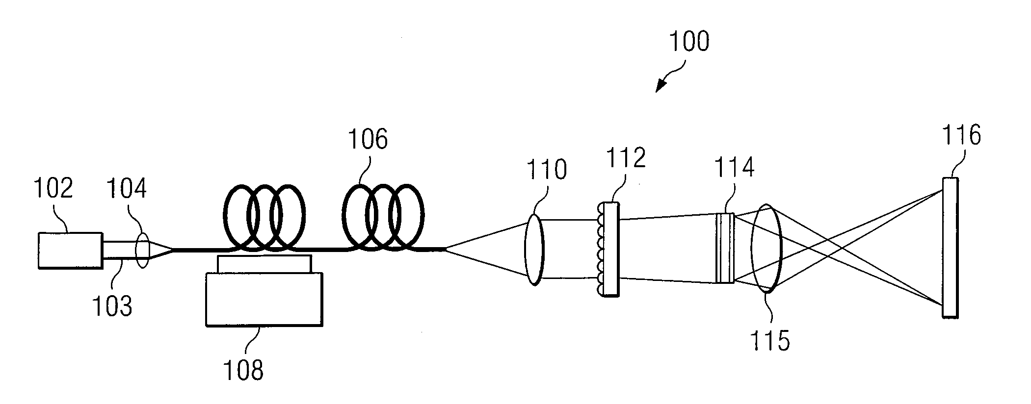
[0004]According to one embodiment, a method for reducing speckles in an image produced from a coherent source of radiation is provided. The method includes coupling a source beam received from a coherent optical source into a multimode optical fiber. A position of at least a portion of the fiber may be modulated using a ditherer. The source beam may be refracted in a lens after it is decoupled from the optical fiber, such that the source beam is aimed at a microlens diffuser. In accordance with a particular embodiment, the source beam may be projected from the microlens diffuser onto a spatial modulator that generates the image. The spatial modulator may be positioned to project the source beam via an imaging lens, to a target.
[0006]Some embodiments of the invention provide numerous technical advantages. Some embodiments may benefit from some, none, or all of these advantages. For example, according to one embodiment, sources of coherent light may be used to produce images with improved speckle contrast. Noticeable grainy patterns underlying the image may be reduced, and thus, viewer satisfaction with the imaging system may be improved.
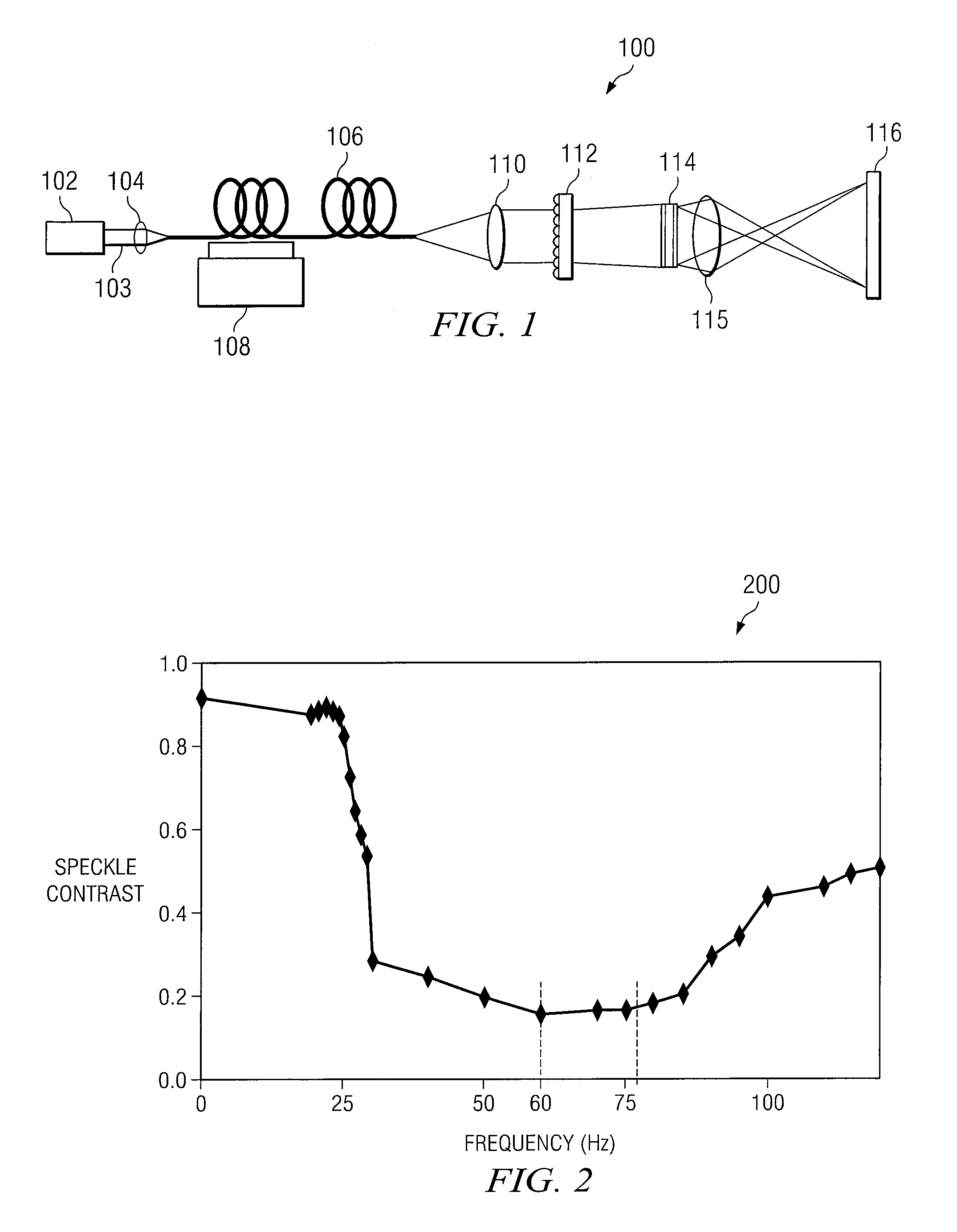
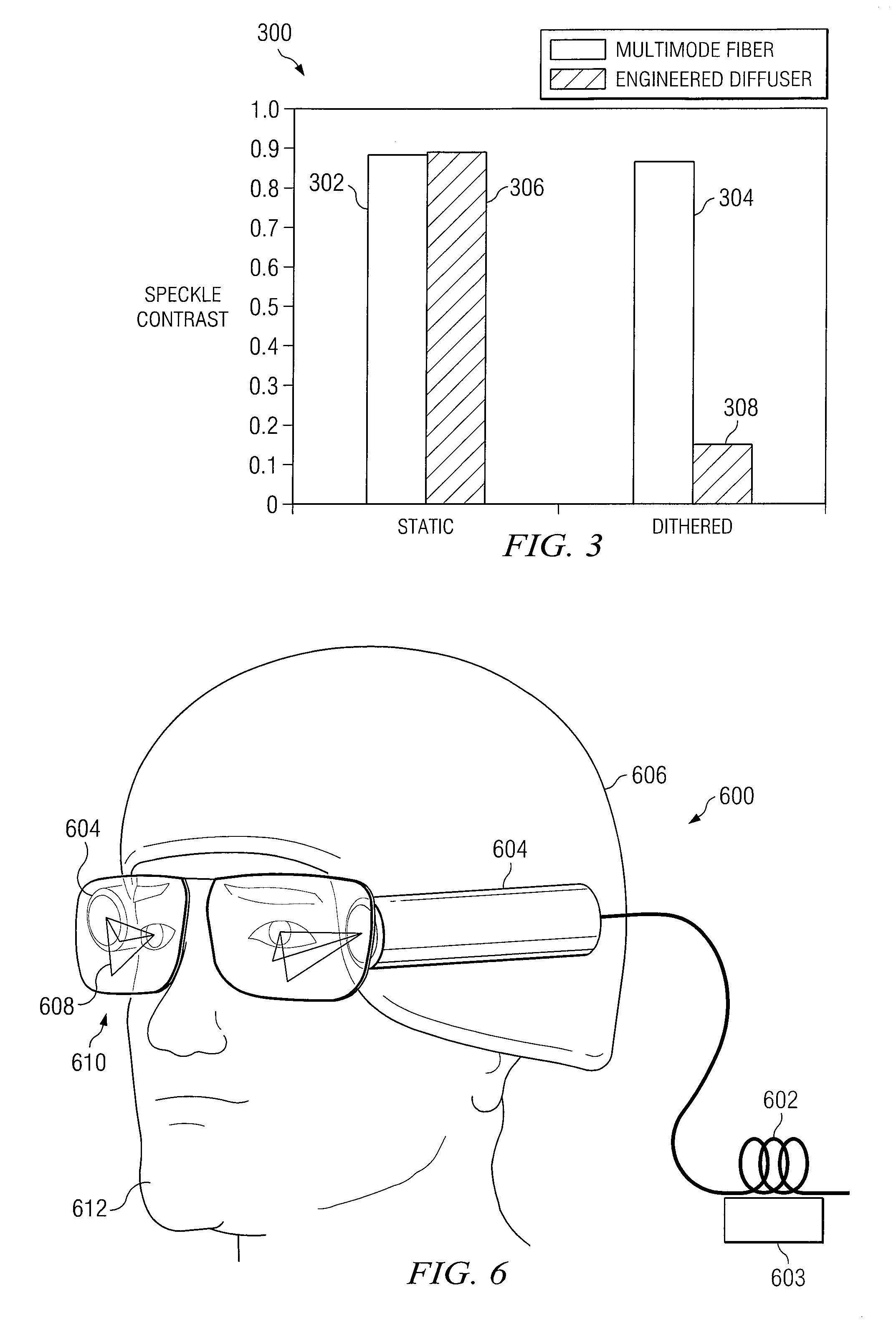
[0007]Specifically, an advantage may be that speckles caused by the inherent properties of multimode optical fibers may be reduced. By modulating the position of the multimode optical fiber, the power distribution in each mode sustained by the optical fiber may be altered. In particular embodiments, the position modulation of the optical fiber may be controlled by dithering using an electromechanical ditherer such that by applying a voltage selectively, a predictable reduction in speckle contrast will result.
[0008]Still another advantage may be that, speckles introduced into an image due to surface roughness, of the display target may be reduced. For example, a microlens array may be used, in particular embodiments, to provide beam homogenization and arbitrary illumination profile conversion. The microlens array may convert a beam of coherent radiation into a multitude of beamlets that diverge to overlap each other on the screen, diffuser, combiner, or other target display.
[0010]Still another advantage may be speckle reduction in images produced by head-up and / or head-mounted imaging systems. For example, the bright and dark spots that are typically present in the lines, characters, and symbols that make up the projected picture in such systems may be reduced. As a result, the image may appear more continuous to the viewer, greater detail density becomes possible and smaller objects become more apparent.

Problems solved by technology

However, picture quality may still suffer since sources of coherent light often produce images having a noticeable pattern underlying the image.
Because in phase electromagnetic radiation results in light-wave fronts arriving at a target or display at the same time, upon interaction with the target surface the individual light waves interfere with one another.
If this surface is rough and imperfectly smooth then the interference between the light waves interferes constructively and destructively thus forming a pattern of bright and dark fringes, and an image may appear grainy to a viewer.

Method used


Image

  • System and Method for Despeckling an Image Illuminated by a Coherent Light Source
  • System and Method for Despeckling an Image Illuminated by a Coherent Light Source
  • System and Method for Despeckling an Image Illuminated by a Coherent Light Source

Examples


Embodiment Construction

[0019]Particular embodiments of the invention and its advantages are best understood by referring to FIGS. 1-6 of the drawings, like numerals being used for like and corresponding parts of the various drawings.

[0020]When a light beam produced by a coherent source of radiation, such as that from a laser, is projected for viewing, a noticeable pattern may underlie the projected image. The underlying pattern, also known as “speckle,” cannot be easily accommodated by the human eye. As a result, the projected image may appear grainy to the viewer. For example, when a coherent source of radiation is used to project an image in a head-up or head-mounted display system, the lines, characters, and symbols that make up the projected image may include bright and dark spots. The projected symbology may also appear broken-up instead of continuous.

[0021]A speckle pattern is a granular intensity pattern produced by the mutual interference of a set of wavefronts in the eye retina or on a camera due...


PUM


Abstract

A method and system for reducing speckle in an image produced from a coherent source of radiation is provided. The method includes coupling a source beam received from a coherent optical source into an optical fiber. A position of at least a portion of the fiber may be modulated using a ditherer. The source beam may be refracted by a lens after it is decoupled from the optical fiber, such that the source beam is aimed at a microlens diffuser. In accordance with a particular embodiment, the source beam may be projected from the microlens diffuser onto a spatial modulator. The spatial modulator may be positioned to project the source beam via an imaging lens, to a target.

Description

RELATED APPLICATIONS[0001]This application claims priority to U.S. Ser. No. 61 / 093,626, entitled SPECKLE FREE LASER GENERATED IMAGE OBTAINED BY MICROLENS ARRAY WITH DITHERED MULTIMODE FIBER, and filed on Sep. 2, 2008, which is hereby incorporated by reference.TECHNICAL FIELD OF THE INVENTION[0002]This invention relates generally to imaging systems and more particularly to a system and method for reducing speckle in an image illuminated by a coherent light source.BACKGROUND OF THE INVENTION[0003]To improve the resolution and brightness of imaging systems and to provide better picture quality, sources of coherent light such as lasers may be used in the place of sources of incoherent light such as light-emitting-diodes (LEDs) and lamps. However, picture quality may still suffer since sources of coherent light often produce images having a noticeable pattern underlying the image. This underlying pattern, also known as speckle, arises due to the high coherence of the source light. Lasers...

Claims


Application Information

Patent Timeline
Patent Type & Authority Applications(United States)
IPC IPC(8): G02B26/00
CPCG02B3/0006G02B6/02G02B6/14H04N9/3197G02B27/48G02B2027/0118H04N9/3161G02B27/0172H01S3/005
Inventor TILLEMAN, MICHAEL M.TRAYNOR, JOSEPH THOMAS
Owner ELBIT SYSTEMS OF AMERICA LLC
Learn More