Circuit for reading a charge retention element for a time measurement
a charge retention element and time measurement technology, applied in the field of electronic circuits, can solve the problems of limited measurable time range and inability to easily compatible with memory manufacturing steps, and the solution of the above-mentioned document is known
- Summary
- Abstract
- Description
- Claims
- Application Information
AI Technical Summary
Benefits of technology
Problems solved by technology
Method used
Image
Examples
first embodiment
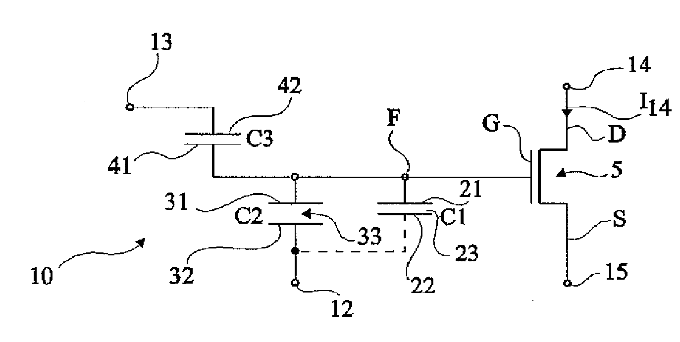
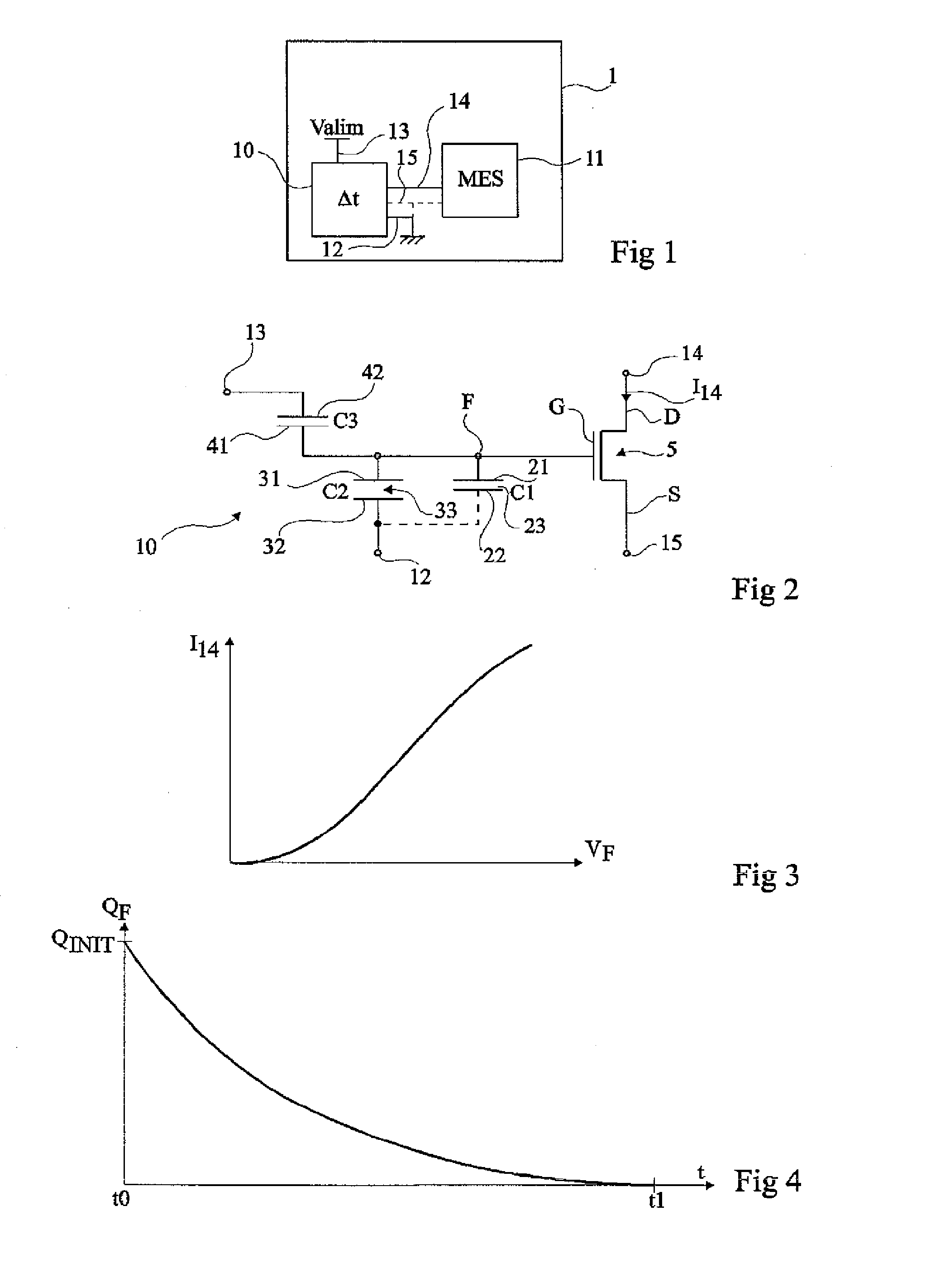
[0052]FIG. 2 shows the electric diagram of a controllable charge retention circuit 10 according to the first aspect of the present invention.
[0053]Circuit 10 comprises a first capacitive element C1 having a first electrode 21 connected to a floating node F and having its dielectric spacer 23 designed (by its permittivity and / or by its thickness) to have leakages which are not negligible with time. “Floating node F” is used to designate a node which is not directly connected to any diffused region of the semiconductor substrate and, more specifically, which is separated by a dielectric spacer, from any voltage-application terminal. By default, second electrode 22 of capacitive element C1 is either connected (dotted lines in FIG. 2) to terminal 12 intended to be connected to a reference voltage, or left unconnected.
[0054]A second capacitive element C2 has a first electrode 31 connected to node F and a second electrode 32 connected to terminal 12. Dielectric spacer 33 of capacitive ele...
second embodiment
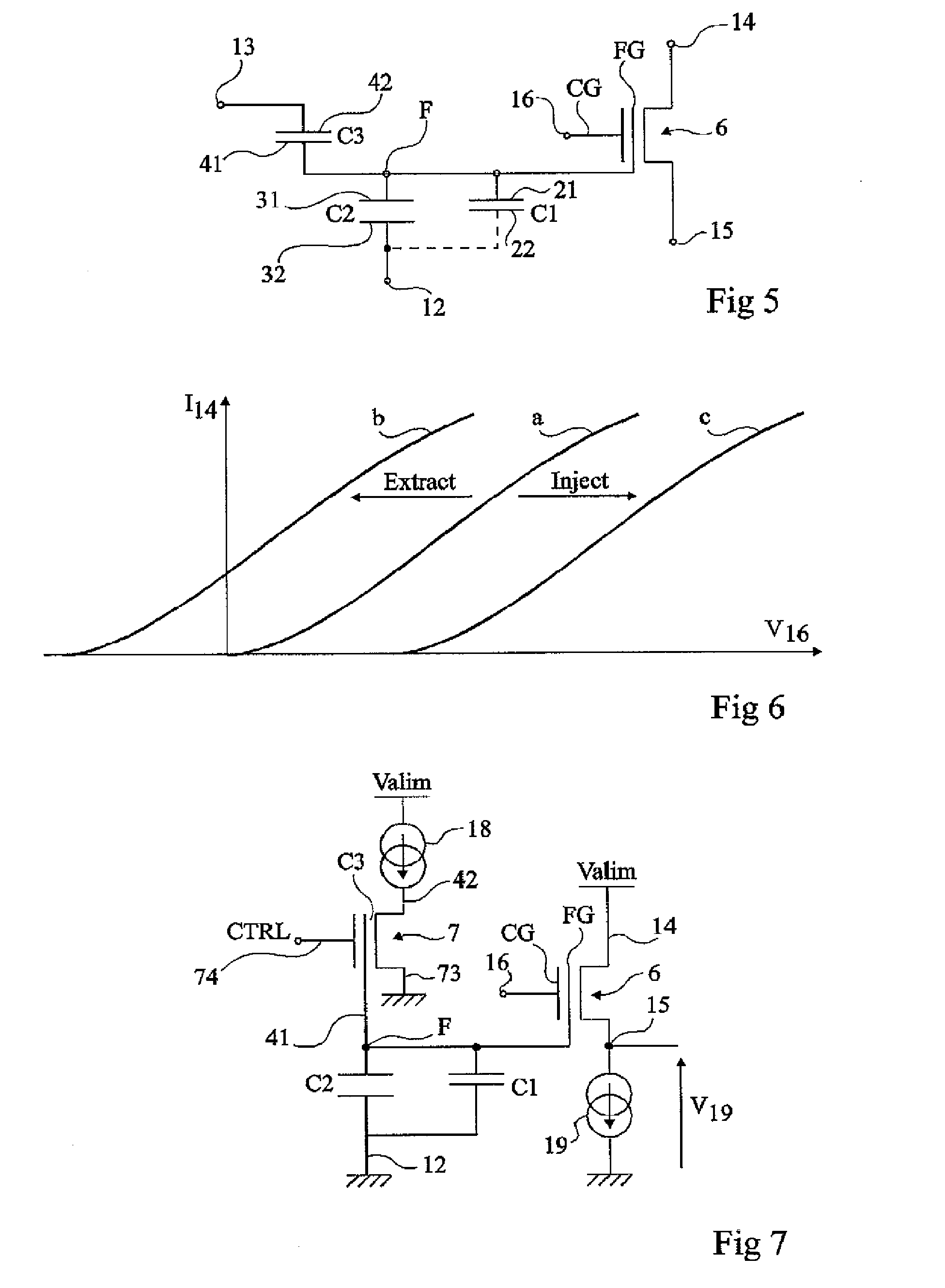
[0067]FIG. 5 shows a circuit according to the present invention. As compared with the embodiment of FIG. 2, transistor 5 is replaced with a transistor 6 with a floating gate FG connected to node F. Control gate CG of transistor 6 is connected to a terminal 16 of control in read mode of the residual charge in the circuit.
[0068]FIG. 6 illustrates, in a graph of current I14 versus voltage V16 applied on the control gate, the operation of the circuit of FIG. 5. It is assumed that the voltage at drain and source terminals 14 and 15 of transistor 6 is maintained constant by an external read circuit (11, FIG. 1). The voltage drop between the floating gate and terminal 15 then depends on the electric charge present at node F, on the total capacitance between nodes F and 12 (essentially capacitances C1 and C2), and on the voltage applied on control terminal 16 of transistor 6. In FIG. 6, three curves a, b, and c have been illustrated. Curve a shows the case where node F is totally discharged...
PUM
 Abstract
Description
Claims
Application Information
 - R&D
- Intellectual Property
- Life Sciences
- Materials
- Tech Scout
- Unparalleled Data Quality
- Higher Quality Content
- 60% Fewer Hallucinations
Browse by: Latest US Patents, China's latest patents, Technical Efficacy Thesaurus, Application Domain, Technology Topic, Popular Technical Reports.
© 2025 PatSnap. All rights reserved.Legal|Privacy policy|Modern Slavery Act Transparency Statement|Sitemap|About US| Contact US: help@patsnap.com


