
Gas container corrosion protection

a corrosion protection and gas container technology, applied in the field of gas storage, can solve the problems of water based seals, corrosion, frequent maintenance, etc., and achieve the effect of preventing corrosion, reducing the use time of materials, and preventing corrosion

Inactive Publication Date: 2010-03-04
NGRID INTPROP
View PDF4 Cites 2 Cited by
  • Summary
  • Abstract
  • Description
  • Claims
  • Application Information

AI Technical Summary

Benefits of technology

[0031]It is also known in certain (non-maintenance) contexts to try to eliminate tank corrosion immediately in contact with the water seal by eliminating oxygen from the seal, or to reduct water vapors from entering the stored gas. (This was important when gas was manufactured locally.) Such techniques fail to provide an alternative to original painting methods.

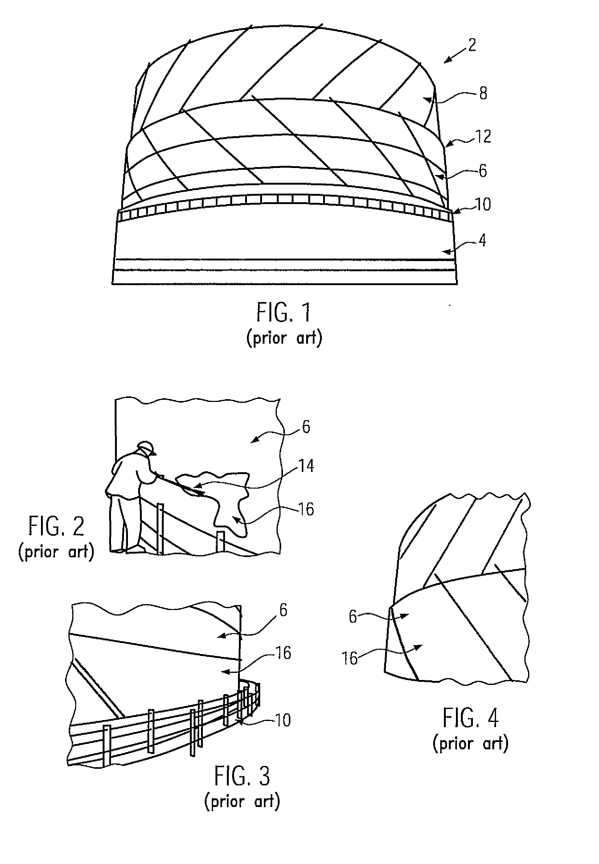
Problems solved by technology

A problem with known systems is that the water based seals, in which a part of a (substantially cylindrical) upper container is in contact with water, are subject to corrosion and need to undergo frequent maintenance, which includes removing and reapplying an anticorrosion coating.
In conventional methods, problems associated with preparation include:
Potential noise pollution during surface preparation—HP and UHP jetting units, compressors, site generators, MEWPs etc.
Material has limited use time before it cures.
In conventional methods, problems associated with performance include:Coating breakdown affects surrounding area.
The full paint system then needs to be applied, involving multiple curing times. It is not adequate to overcoat what's already there.
There is potential for hidden areas of coating breakdown.
Such techniques fail to provide an anti-corrosion coating on to the gas holder by use of the existing ‘water seal’.
Such techniques fail to provide an alternative to original painting methods.

Method used


Image

  • Gas container corrosion protection
  • Gas container corrosion protection
  • Gas container corrosion protection

Examples


Embodiment Construction

[0041]Various embodiments of the present invention provide improved techniques for storage of gases.

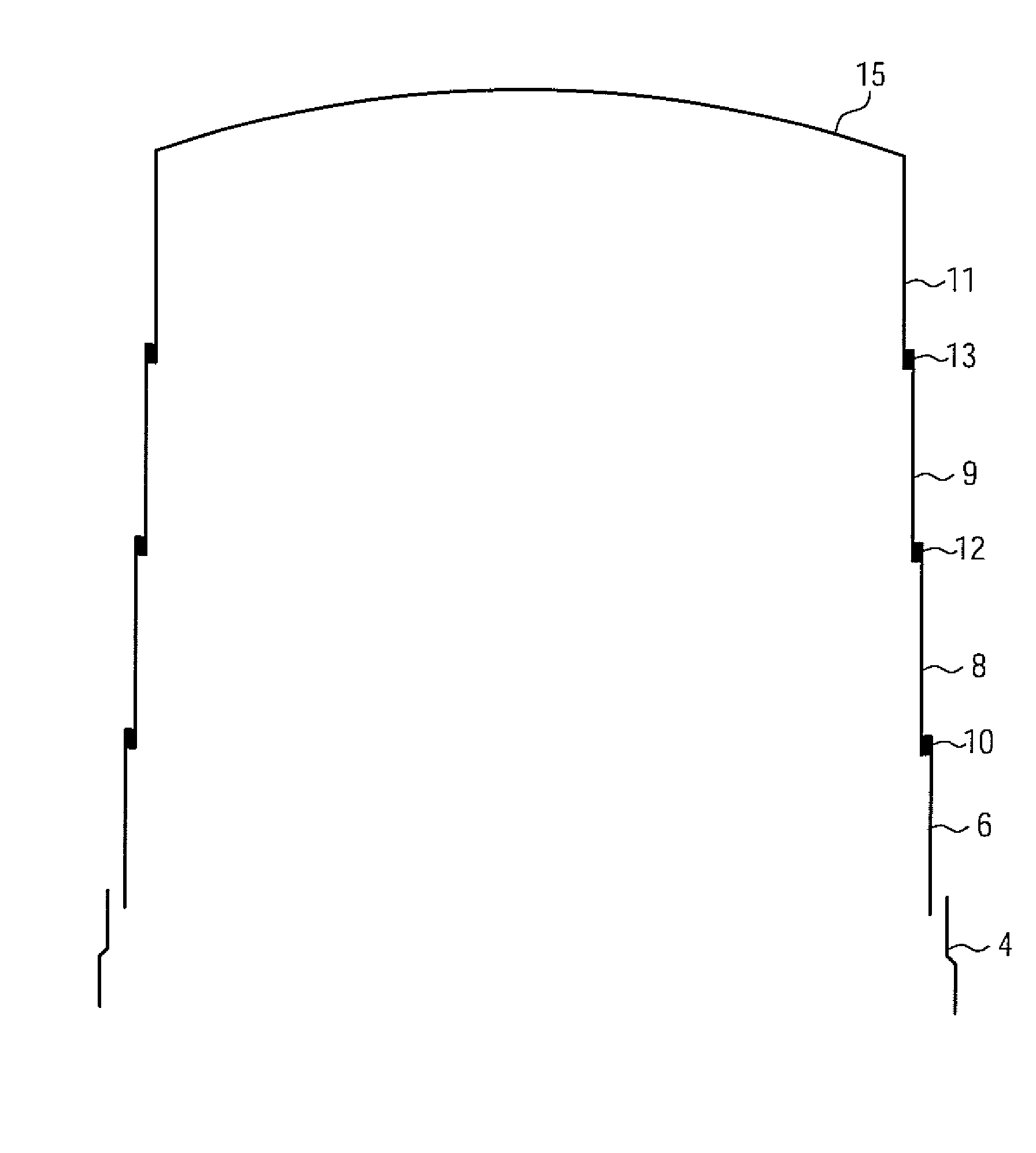
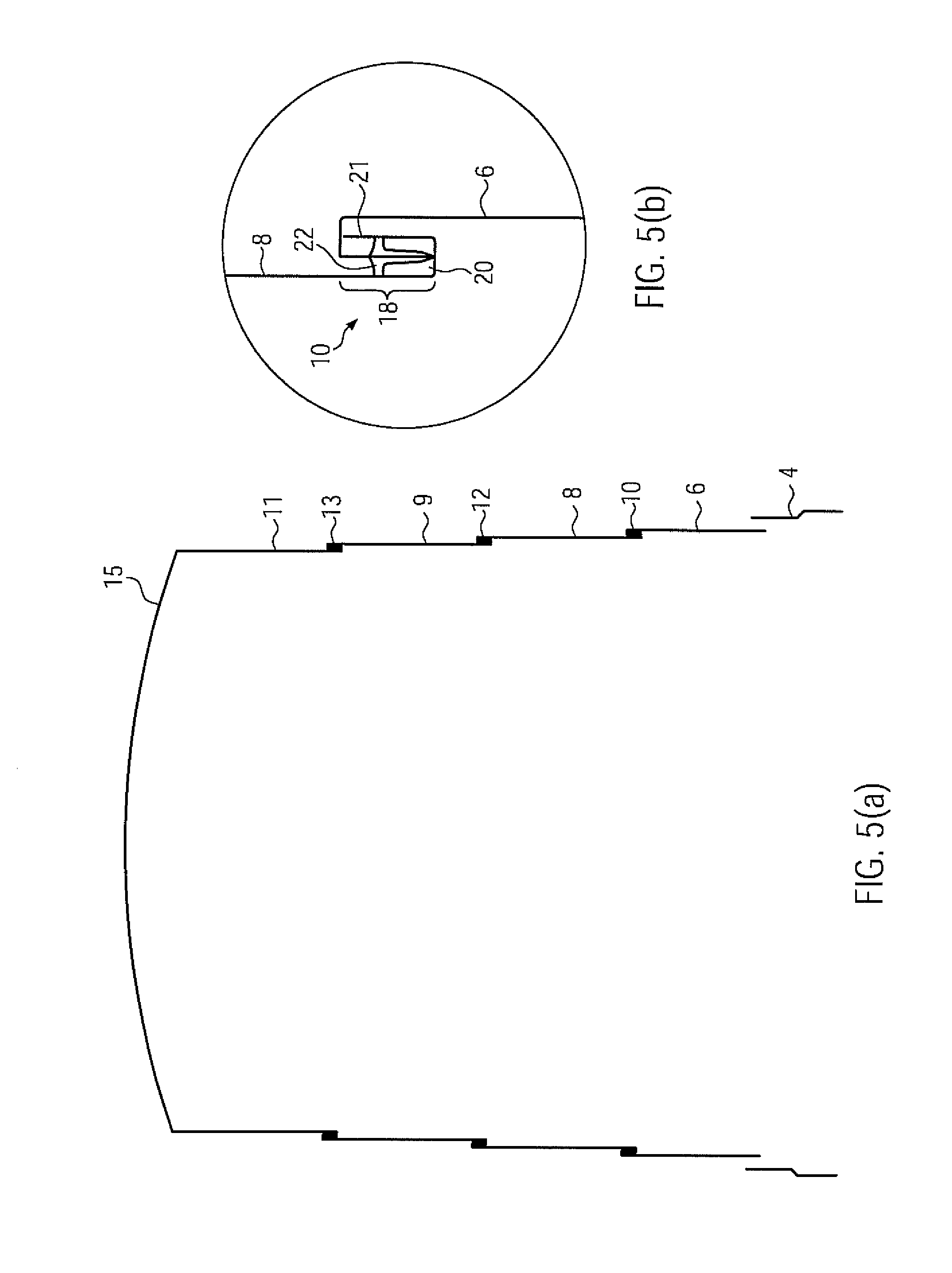
[0042]According to one aspect of the present invention there is provided a gas container, comprising: at least a first section and a second section, the first and second sections being substantially hollow and movable relative to each other; a liquid seal for sealing gas within the container, the liquid seal being disposed between the first section and the second section; wherein a first anti-corrosion coating is provided so as to float on the surface of the liquid in said liquid seals; whereby, in use, the first anti-corrosion coating is caused to be applied to at least a portion of said second section during motion of the second section relative to the first section.

[0043]Preferably, the second section has a second anti-corrosion coating on at least a portion thereof. Preferably, the first anti-corrosion coating is caused to be applied to at least a part of said second anti-corrosio...


PUM

PropertyMeasurementUnit
thicknessaaaaaaaaaa
anti-corrosion aaaaaaaaaa
anti-corrosionaaaaaaaaaa

Abstract

A gas container and method of maintaining gas in a container and assembling a gas container are provided. The gas container includes at least a first section and a second section with the first and second sections being substantially hollow and movable relative to each other and a liquid seal for sealing gas within the container. The liquid seal is disposed between the first section and the second section, wherein a first anti-corrosion coating is provided so as to float on the surface of the liquid in the liquid seals, such that in use, the first anti-corrosion coating is caused to be applied to at least a portion of the second section during motion of the second section relative to the first section.

Description

CROSS REFERENCE TO RELATED APPLICATIONS[0001]This application claims priority to and the benefit of the filing date of Great Britain Patent Application No. GB 0814476.7, filed Aug. 27, 2008, which is hereby incorporated by reference in its entirety.BACKGROUND OF THE INVENTION[0002]The present invention relates to the storage of gas, and more particularly to techniques for preventing or reducing corrosion in gas containers.[0003]It is well known that certain gases, especially combustible gases for domestic or industrial use, and other volatile gases, need to be safely and securely stored, typically by means of traditional bell holders or enlargeable metal gas holder (hereafter “gas holders”) that use a liquid such as water to provide seals for containing the gas.[0004]Gas holders are essential to the continuous supply of gas to customers during periods of high demand. There are currently numerous gas holders deployed, of which many are the water-sealed type. These operate in a harsh ...

Claims


Application Information

Patent Timeline
Patent Type & Authority Applications(United States)
IPC IPC(8): C23F11/00B65D85/00B23P25/00
CPCF17C1/10Y10T29/49885F17C2201/0119F17C2201/0123F17C2201/0176F17C2201/032F17C2201/054F17C2201/056F17C2203/0604F17C2203/0607F17C2203/0621F17C2205/018F17C2209/225F17C2209/232F17C2223/0123F17C2260/013F17C2260/053F17C2201/0109F17B1/00F17B1/007F17B1/02F17B1/04F17B1/06F17B1/16F17B1/20F17C3/12
Inventor WILLIAMS, MARK STEPHEN
Owner NGRID INTPROP
Learn More