Battery cooling device, battery attached with cooling device, and vehicle

a battery and cooling device technology, applied in the field of battery cooling, can solve the problems of large heat generation of the battery mounted in the vehicle, and achieve the effects of convenient cooling, efficient use of energy, and excellent battery characteristics

Inactive Publication Date: 2010-03-04
TOYOTA JIDOSHA KK
View PDF1 Cites 20 Cited by
  • Summary
  • Abstract
  • Description
  • Claims
  • Application Information

AI Technical Summary

Benefits of technology

[0033]The above vehicle comprises one of the above battery cooling devices in addition to the engine and the battery(s). Accordingly, the battery(s) can be cooled easily by operation of the engine.
[0034]Consequently, this vehicle can be achieved as a vehicle mounted with the battery(s) having excellent battery characteristics while efficiently using energy resulting from the engine operation.

Problems solved by technology

Of such batteries, a battery mounted in a vehicle tends to generate a large amount of heat and thus needs a cooling device in many cases.

Method used


Image

  • Battery cooling device, battery attached with cooling device, and vehicle
  • Battery cooling device, battery attached with cooling device, and vehicle
  • Battery cooling device, battery attached with cooling device, and vehicle

Examples


first embodiment

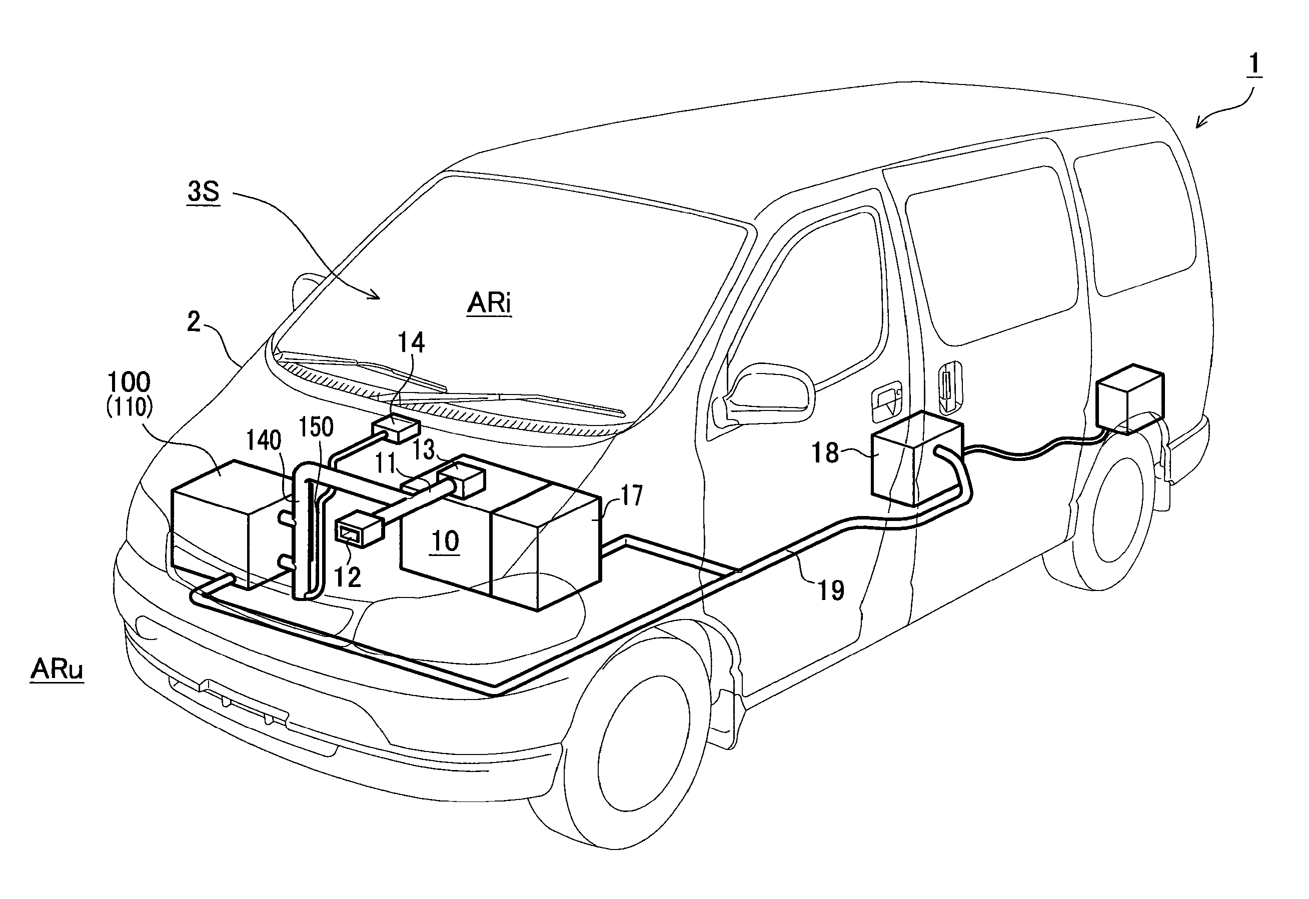
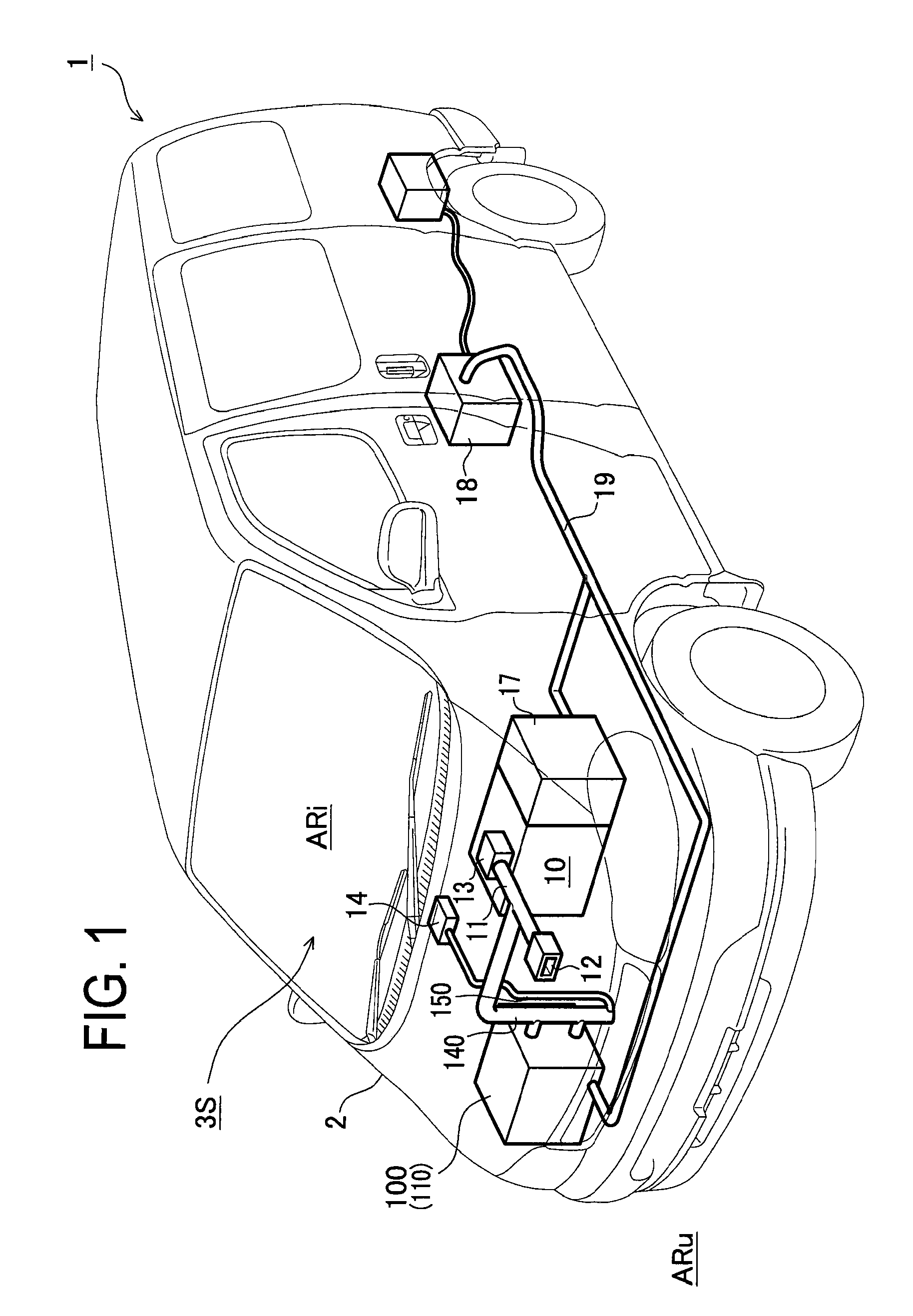
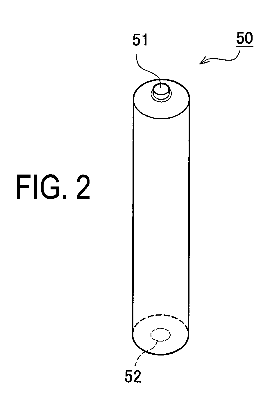
[0081]A vehicle 1 in the first embodiment is a hybrid car which is driven by a combination of an engine 10, a front motor 17, and a rear motor 18 as shown in FIG. 1. This vehicle 1 includes a vehicle body 2, the engine 10, the front motor 17 attached to this engine 10, the rear motor 18, a cable 19, and a battery attached with cooling device 100. This battery attached with cooling device 100 is mounted in the vehicle body 2 of the vehicle 1 and is connected to the front motor 17 and the rear motor 18 through the cable 19. This battery attached with cooling device 100 is constituted of a battery cooling device 110 (a cooling device of battery) which will be mentioned later and a plurality of batteries 50 (only eight batteries are illustrated in FIG. 4) housed in a battery housing chamber 120 formed by a battery housing case 121 as shown in FIG. 3.

[0082]This vehicle 1 is arranged to run by the engine 10, the front motor 17 and the rear motor 18 by a publicly known technique. The vehic...

second embodiment

[0109]A second embodiment will be explained referring to FIGS. 6 and 7.

[0110]A battery attached with cooling device 200 in the second embodiment differs from the battery attached with cooling device 100 in the above first embodiment in regard to a structure of a refrigerant flowing part 230 (fluid flowing means) of a battery cooling device 210, the kinds of fluid, and a drive technique to flow the fluid; however, they are identical in the batteries 50 in addition to a vehicle 21 that is a hybrid car to be driven by a combination of the engine 10 and the motors 17 and 18. Therefore, the explanation will be focused on the different parts from the first embodiment and the identical parts are omitted or briefly explained.

[0111]The vehicle 21 in the second embodiment has the battery attached with cooling device 200 as shown in FIG. 6. This battery attached with cooling device 200 is mounted in the vehicle body 2 of the vehicle 21 and connected to the front motor 17 and the rear motor 18 ...

first modified example

[0124]A first modified example will be explained below referring to FIGS. 6 and 8.

[0125]A battery cooling device 310 in this modified example differs from the battery cooling device 210 in the above second embodiment in relation to the type of fluid, part of a configuration of a battery housing container 321 and an addition of a gas vent valve 325 of a battery housing chamber 320 in the refrigerant flowing part 230 (the fluid flowing means). In the second embodiment, in the circulation passage 270R, the ammonia NH is compressed by the compressor 250 and cooled and liquefied by the heat exchanger 260, and vaporized by the evaporator 280, and then flowed into the battery housing chamber 220. On the other hand, the first modified example is different in a configuration that, in a circulation passage 370R, an antifreeze solution CL cooled through a heat exchanger 360 is flowed into the battery housing chamber 320 by a pump 350.

[0126]However, a drive technique of flowing the fluid by rot...


PUM

PropertyMeasurementUnit
pressureaaaaaaaaaa
temperatureaaaaaaaaaa
energyaaaaaaaaaa

Abstract

Provided are a battery cooling device utilizing intake air or exhaust gas of an engine, a battery having a cooling device attached to it, and a vehicle mounted with the battery cooling device and an engine. The battery cooling device has a battery housing chamber capable of housing a battery and filled with refrigerant, a turbine to be rotated by exhaust gas of the engine, and a refrigerant flow part including a compressor, a heat exchanger a pipe, etc.

Description

CROSS-REFERENCE TO RELATED APPLICATIONS[0001]This is a national phase application filed under 35 U.S.C 371 of PCT / JP2008 / 050932 filed on Jan. 17, 2008, which claims the benefit of priority from the prior Japanese Patent Application No. 2007-014043 filed on Jan. 24, 2007, the entire contents of all of which are incorporated herein by reference.FIELD OF THE INVENTION[0002]The present invention relates to a battery cooling device for cooling a battery by utilizing intake air or exhaust gas of an engine, a battery attached with cooling device including such battery cooling device, and a vehicle mounted with the battery cooling device, the battery, and the engine.BACKGROUND OF THE INVENTION[0003]In recent years, various batteries have been proposed as a power source of a portable device, a mobile phone, etc. or a power source of an electric vehicle, a hybrid car, etc. Of such batteries, a battery mounted in a vehicle tends to generate a large amount of heat and thus needs a cooling devic...

Claims


Application Information

Patent Timeline
Patent Type & Authority Applications(United States)
IPC IPC(8): H01M10/50B60K6/28H01M10/60B60K11/06B60L50/16H01M10/613H01M10/625H01M10/643H01M10/6563H01M10/6568H01M10/6569H01M10/663
CPCB60K1/04B60K2001/005H01M10/5004H01M10/5079H01M10/503H01M10/5077H01M10/5016H01M10/625H01M10/6568H01M10/6569H01M10/643H01M10/613Y02E60/10
Inventor KIMURA, KENJI
Owner TOYOTA JIDOSHA KK
Why Eureka
Try Eureka