Detecting quench in a magnetic resonance examination system

a magnetic resonance examination and quench detection technology, applied in the direction of superconducting magnets/coils, magnetic field measurement using superconductive devices, instruments, etc., can solve the problem that the prior art quench detection methods are not suitable to ensure reliability, and achieve the effect of reducing local heating in the region where the quench started and safe ramming

Inactive Publication Date: 2010-03-04
KONINKLIJKE PHILIPS ELECTRONICS NV
View PDF5 Cites 12 Cited by
  • Summary
  • Abstract
  • Description
  • Claims
  • Application Information

AI Technical Summary

Benefits of technology

[0016]According to a preferred embodiment of the invention the detecting device is adapted to control a protecting means to protect the main magnet in case of a quench. In particular the detecting means is adapted to disconnect the power supply of the main magnet if an emerging quench is detected. Preferably the detecting device is adapted to operate a switch to disconnect the power supply of the main magnet in such a case. The magnetic resonance examination system is preferably arranged in a way, that the main magnet is ramped-down safely by dissipating the stored electromagnetic energy outside the main magnet's windings. This means limits an uncontrolled dissipation of the electromagnetic energy in the main magnet's windings, which can damage or destroy the main magnet. Instead, most of the magnetic energy is safely dissipated in special resistors.
[0017]Preferably, the magnetic r

Problems solved by technology

However, the arrangement of the magnetic field gradient system outside of the main magnet of the magnetic resonance examination system may induce voltages in the main magnet, which could misleadingly be inte

Method used


Image

  • Detecting quench in a magnetic resonance examination system
  • Detecting quench in a magnetic resonance examination system
  • Detecting quench in a magnetic resonance examination system

Examples


Embodiment Construction

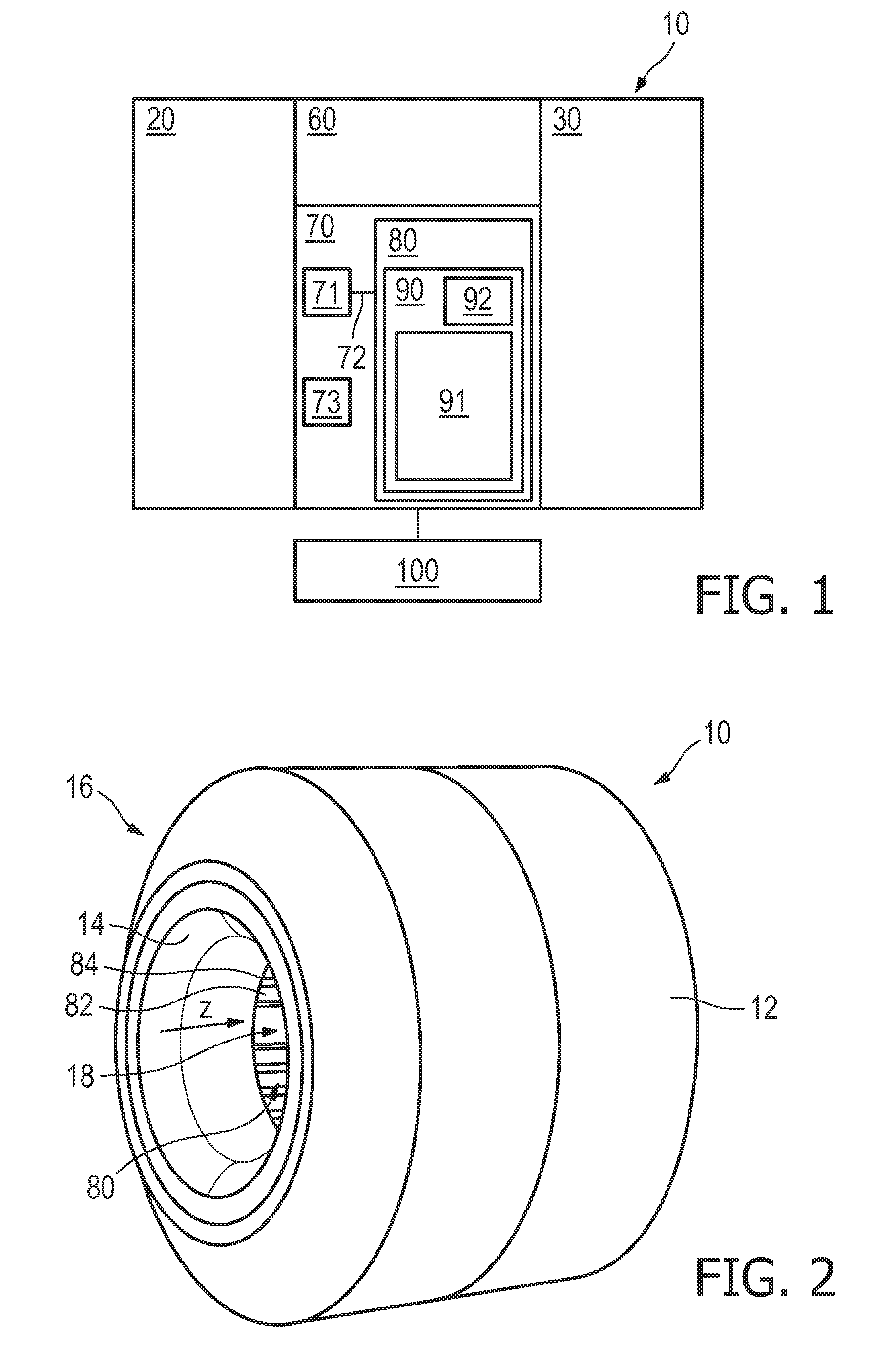
[0030]As illustrated in FIG. 1, the magnetic resonance imaging (MRI) scanner 10 comprises a superconducting main magnet 20, which surrounds an examination region 18 (see FIG. 2) and generates a main magnetic field in the examination region 18. Furthermore the MRI scanner 10 comprises a magnetic field gradient system 30 that enables spatial localization of the MRI signals. The magnetic field gradient system 30 selectively causes alternating gradient magnetic fields in the examination region 18, and is disposed outside of the main magnet 20, as described below in more detail. Furthermore the MRI scanner 10 comprises a radio frequency (RF) system 60 that transmits energy and receives signal information, and a computer system 70 to control the scanner's components and subsystems.

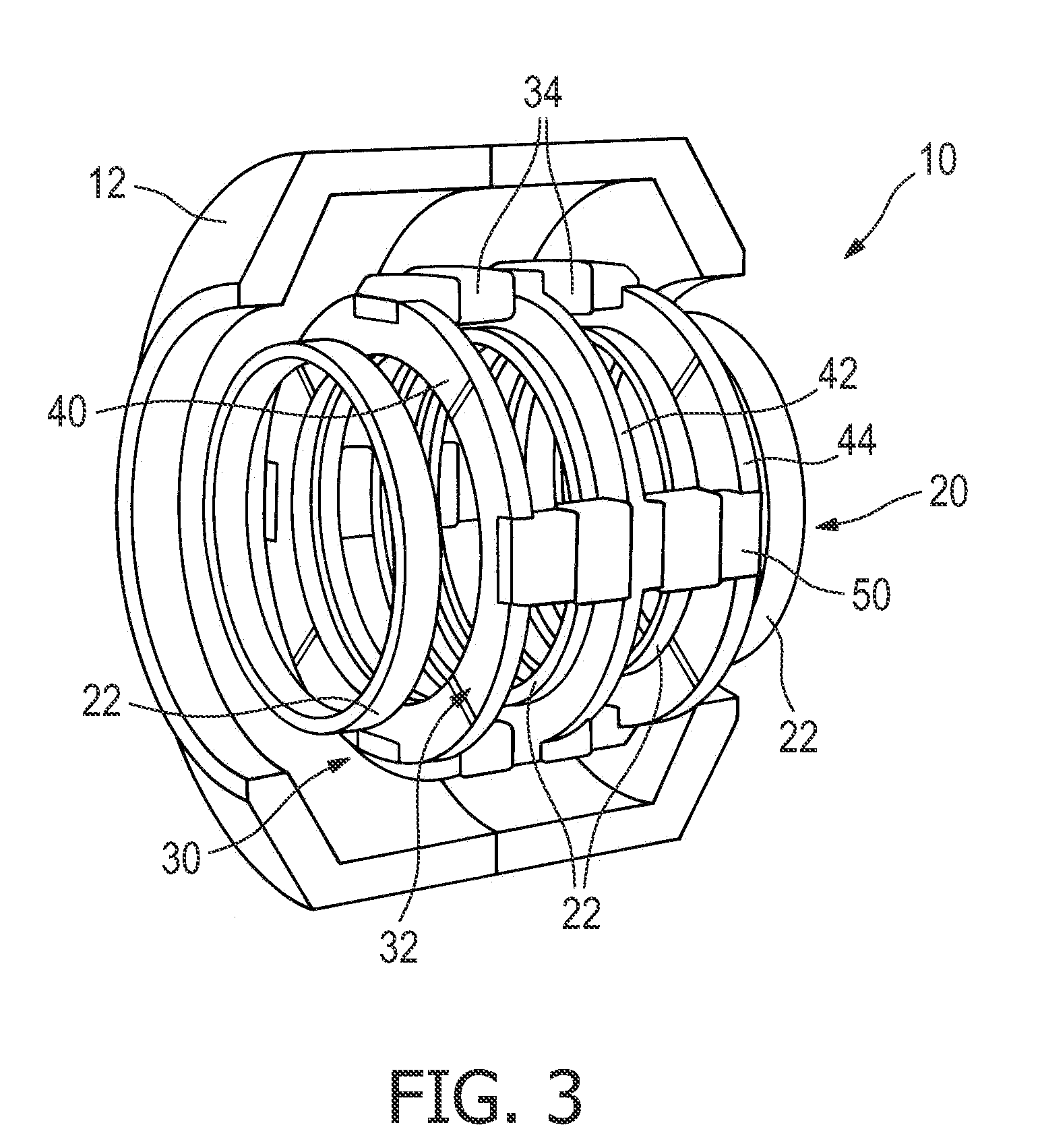
[0031]With reference to FIGS. 2 and 3, the MRI scanner 10 includes a housing made up of an outer flux return shield 12 and an inner bore tube 14. The outer flux return shield 12 and the inner bore tube 14 are se...


PUM


Abstract

The present invention relates to a magnetic resonance examination system (10) and to a method of operating such a magnetic resonance examination system (10). In particular the present invention relates to a magnetic resonance examination system (10) comprising a superconducting main magnet (20) surrounding an examination region (18) and generating a main magnetic field in the examination region (18), and further comprising a magnetic field gradient system (30) selectively causing alternating gradient magnetic fields in the examination region (18), said magnetic field gradient system (30) being coupled to the main magnet (20). In order to provide a technique to reliably detect a quench of the superconducting main magnet (20) of such a magnetic resonance examination system (10) a detecting device (91) is suggested for detecting an emerging quench of the main magnet (20), said detecting device (91) being adapted to operate in different modes depending on the mode of operation of the magnetic resonance examination system (e.g. ramp-up, ramp-down or continuous operation).

Description

FIELD OF THE INVENTION[0001]The present invention relates to a magnetic resonance examination system and to a method of operating such a magnetic resonance examination system. In particular the present invention relates to a magnetic resonance examination system comprising a superconducting main magnet surrounding an examination region and generating a main magnetic field in the examination region, and further comprising a magnetic field gradient system selectively causing alternating gradient magnetic fields in the examination region, said magnetic field gradient system being coupled to the main magnet.BACKGROUND OF THE INVENTION[0002]Recently, new magnetic resonance examination system designs have been proposed, in which the main magnet system comprises magnet coils of superconductive material, and in which the magnetic field gradient system is located at the outside of the superconducting coil system and a weak-iron flux conduction system is provided to guide the magnetic gradien...

Claims


Application Information

Patent Timeline
IPC IPC(8): G01R33/035
CPCG01R33/288H01F6/02G01R33/3815
Inventor TIMINGER, HOLGEROVERWEG, JOHANNES ADRIANUS
Owner KONINKLIJKE PHILIPS ELECTRONICS NV
Why Eureka
Try Eureka