Vital sign monitor system and method

a sign and monitor technology, applied in the field of vital sign monitoring system, can solve the problems of large and typically not portable, cumbersome and heavy to be attached to the patient's wrist without severely hampering the patient's movement, and many artefacts and other noise being introduced into the patient's body, so as to reduce the amount, inhibit the use of the patient's hand, and improve the effect of pulse detection

Inactive Publication Date: 2010-03-04
TELEMEDIC
View PDF10 Cites 114 Cited by
  • Summary
  • Abstract
  • Description
  • Claims
  • Application Information

AI Technical Summary

Benefits of technology

[0005]The present invention overcomes the above and other drawbacks by providing a portable vital sign monitor, comfortable to the patient and mountable on either hand while at the same time minimising the amount by which use of the patient's hands are restricted by the monitor. The conventional finger tip SpO2 monitoring (requiring a support / sensing assembly on a finger and an interconnecting cable between sensor and processing device) which greatly inhibits the use of the patient's hand has been done away with. It is also an object of the invention to provide a palm vital sign sensor in a location which allows for improved pulse detection.

Problems solved by technology

One draw back with such prior art sensors is that they are large and typically not portable.
In the case that they are portable such prior art monitors are cumbersome and too heavy to be attached to a patient's wrist without severely hampering the patient's movement.
Another drawback is that the positioning of the sensor on the end of a patient's ginger leads to many artefacts and other noise being introduced into the signals collected by the sensor as a result of articulation of the patient's fingers.
Additionally, the positioning of the sensor on the finger tip effectively prohibits use of that finger, thereby reducing patient mobility.
Still another drawback is that such portable devices do not provide wireless interconnection with other devices, such as data processing, networking and storage equipment, thereby reducing the potential of remote monitoring of a patient's condition and the like.

Method used


Image

  • Vital sign monitor system and method
  • Vital sign monitor system and method
  • Vital sign monitor system and method

Examples


Embodiment Construction

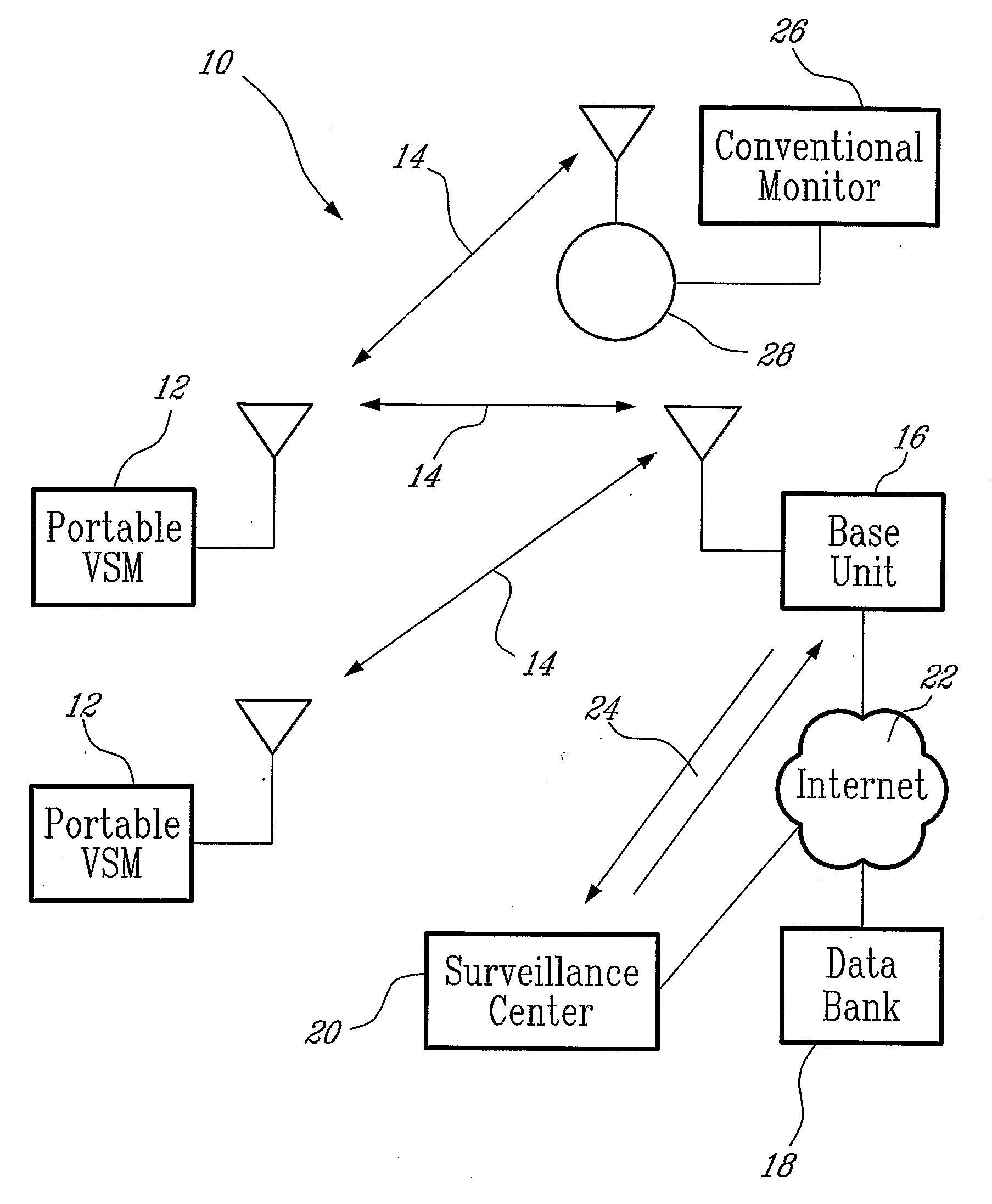
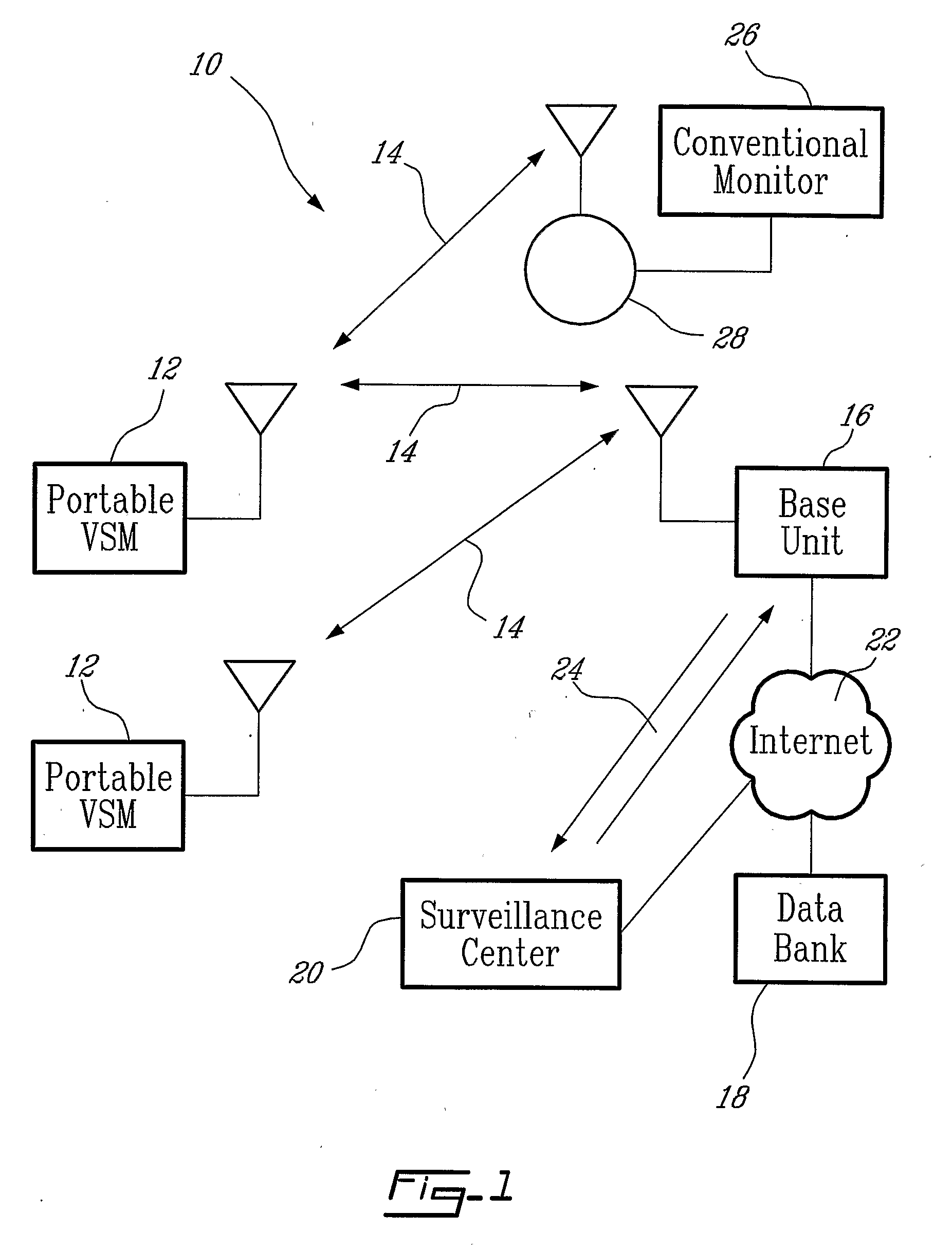
[0021]Referring now to FIG. 1, there is disclosed in accordance with an illustrative embodiment of the present invention a vital sign monitoring system, generally referred to using the reference numeral 10. The system is comprised of one or more portable vital sign monitors as in 12 which communicate via radio frequency (RF) connections as in 14 with one or more base units as in 16. The base unit 16 provides interconnection with other data processing devices, such as data banks as in 18 or other computing devices for example at a surveillance centre 20, which further process data received from the monitors as in 12 via the base unit(s) as in 16. Illustratively, the interconnection is provided via the internet 22 or alternatively via a dial up connection 24.

[0022]In an alternative embodiment the monitors as in 12 can communicate directly with a conventional vital sign monitor 26 via an RF interface module 28 or other wireless interface such as infrared or the like. In this regard, th...


PUM


Abstract

A portable vital sign monitor is provided which has a palm vital sign monitor unit carried by the patient, the unit comprising an optical probe positioned in the palm of the patient which measures at least one vital sign including SpO2 and pulse rate but not exclusively and only those vital signs. The detected vital signs are stored in memory and transmitted by wireless inter-connection to a communication base unit, which transmits the vital sign by a phone line, LAN, Internet, serial interface or the like to a data processing device / centre.

Description

[0001]The present invention claims the benefit of a commonly assigned provisional application entitled “Portable vital sign monitor”, which was filed on Jul. 9, 2004 and assigned Ser. No. 60 / 586,228. The entire contents of the foregoing provisional patent application are hereby incorporated by reference.FIELD OF THE INVENTION[0002]The present invention relates to a vital sign monitoring system. In particular, the present invention relates to a portable vital sign monitor supported provided with an infra-red optical sensor positioned in the palm of a patient's hand for sensing vital signs such a SpO2, pulse rate and potentially other vital signs. The detected vital signs are stored in memory for later transfer to a centralised server, for example by means of a communication base station and a interposed communication system such as a telephone line, computer network, etc.BACKGROUND TO THE INVENTION[0003]Patient vital sign monitoring may include measurements of blood oxygen, blood pre...

Claims


Application Information

Patent Timeline
Patent Type & Authority Applications(United States)
IPC IPC(8): A61B5/1455A61B5/02
CPCA61B5/0205A61B5/02416A61B5/14546A61B5/1455G06F19/3418A61B5/4884A61B5/6806A61B5/6826A61B5/6838A61B5/14552G16H40/67
Inventor HURTUBISE, JEAN DENISTREMBLAY, DANIELTROTTIER, SYLVAIN
Owner TELEMEDIC
Why Eureka
Try Eureka