Check patentability & draft patents in minutes with Patsnap Eureka AI!

Reference circuit for providing precision voltage and precision current

a reference circuit and voltage technology, applied in the field of reference circuits, can solve the problems of additional control circuits, inefficient space and cost, loop instability and loop oscillation,

Active Publication Date: 2010-03-11
FARADAY TECH CORP
View PDF7 Cites 26 Cited by
  • Summary
  • Abstract
  • Description
  • Claims
  • Application Information

AI Technical Summary

Benefits of technology

[0014]It is therefore one of the objectives of the present invention to provide a reference circuit disposed in an IC circuit for providing both a precision voltage and a precision current with transistors of the reference circuit all operating in saturation regions.
[0015]According to an exemplary embodiment of the present invention, a reference circuit for providing both a precision voltage and a precision current is provided. The reference circuit includes a bandgap voltage reference circuit outputting a bandgap voltage as the precision voltage at a first voltage output terminal and outputting a PTAT current at a current output terminal in response to a power supply; a positive temperature coefficient calibrating circuit connected to the first voltage output terminal and the curr...

Problems solved by technology

In other words, an external precision resistor is required and needs to be additionally disposed on the circuit board, which results in inefficient problems in space and cost.
If the operational amplifier 14 is unstable, the parasitic capacitance on the I / O pad 18 is hard to be estimated, which might result in loop instability and loop oscillation.
However, this system needs an additional control circuit for controlling the resistance.
Although providing a precision current, the abovementioned circuitry does not provide any precision voltage.
In addition, due to possible deviations rendered by mass production in the manufacturing process of the IC circuit, it is difficult to control the transistor M1 to be operated in the triode region.

Method used


Image

  • Reference circuit for providing precision voltage and precision current
  • Reference circuit for providing precision voltage and precision current
  • Reference circuit for providing precision voltage and precision current

Examples


Embodiment Construction

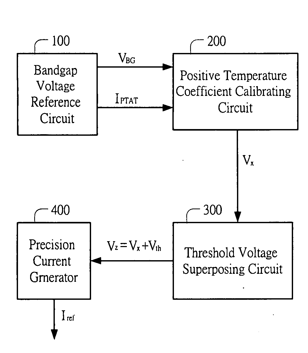
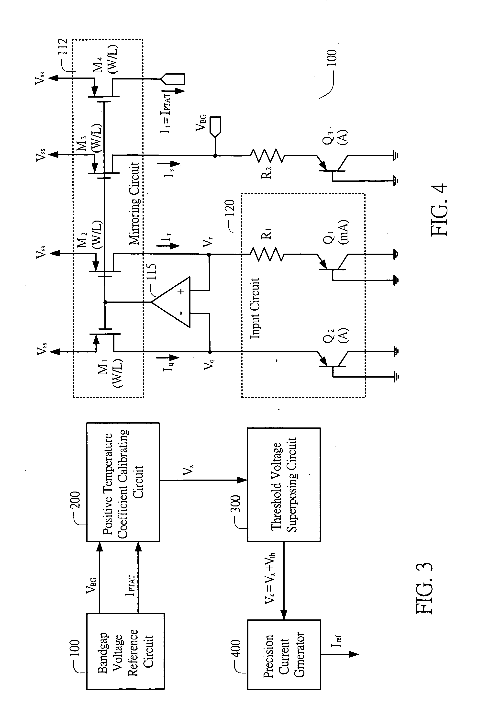
[0024]Please refer to FIG. 3, which is a diagram illustrating a reference circuit capable of providing both a precision voltage and a precision current according to an embodiment of the present invention. The reference circuitry includes a bandgap voltage reference circuit 100, a positive temperature coefficient calibrating circuit 200, a threshold voltage superposing circuit 300, and a precision current generator 400. The details of respective circuits are described hereinafter with reference to FIG. 4˜FIG. 7.

[0025]FIG. 4 illustrates an embodiment of the bandgap voltage reference circuit 100. The bandgap voltage reference circuit 100 includes PMOS field-effect transistors, PNP bipolar transistors and operational amplifiers constituting a first mirroring circuit 112, a first operational amplifier 115 and an input circuit 120. The mirroring circuit 112 includes four PMOS field-effect transistors (FET) M1, M2, M3 and M4. In this embodiment, the four PMOS FETs M1, M2, M3 and M4 have th...


PUM


Abstract

A reference circuit for providing a precision voltage and a precision current includes a bandgap voltage reference circuit, a positive temperature coefficient calibrating circuit, a threshold voltage superposing circuit and precision current generator interconnected in cascade. From the bandgap voltage reference circuit, a bandgap voltage is outputted as the precision voltage, and a PTAT current is outputted to the positive temperature coefficient calibrating circuit along with the bandgap voltage for generating a PTAT voltage. In response to the PTAT voltage from the positive temperature coefficient calibrating circuit, the threshold voltage superposing circuit generates a first voltage which is equal to the PTAT voltage plus a threshold voltage. Then the precision current generator outputs a reference current as the precision current in response to the first voltage.

Description

FIELD OF THE INVENTION[0001]The present invention relates to a reference circuit, and more particularly, to a reference circuit for providing both a precision voltage and a precision current.BACKGROUND OF THE INVENTION[0002]In the design of high-speed I / O circuits such as USB interfaces or SATA interfaces, it is necessary to use a precision voltage and a precision current as references for impedance matching. Please refer to FIG. 1, which is a diagram illustrating a reference circuit capable of providing a precision voltage and a precision current according to prior art. As shown, an IC circuit 10 includes a bandgap voltage reference circuit 12, an operational amplifier 14, a mirroring circuit 16, a transistor M1, and an I / O pad 18.[0003]Generally speaking, the bandgap reference circuit 12 is used for providing a stable bandgap voltage (VBG), which will not change as the manufacturing process, the temperature or the supply voltage changes. Therefore, the bandgap voltage VBG outputte...

Claims


Application Information

Patent Timeline
IPC IPC(8): G05F3/02
CPCG05F3/30
Inventor HUANG, DIN-JIUNCHEN, KUAN-YUCHANG, YUAN-HSUN
Owner FARADAY TECH CORP
Features
  • R&D
  • Intellectual Property
  • Life Sciences
  • Materials
  • Tech Scout
  • Unparalleled Data Quality
  • Higher Quality Content
  • 60% Fewer Hallucinations
Learn More