Camera body and imaging device

a technology for imaging devices and cameras, applied in cameras, television systems, instruments, etc., can solve the problems of reducing affecting the reduction of the size of the camera body, so as to achieve the effect of more compa

Active Publication Date: 2010-03-11
PANASONIC CORP
View PDF4 Cites 13 Cited by
  • Summary
  • Abstract
  • Description
  • Claims
  • Application Information

AI Technical Summary

Benefits of technology

[0014]In this case, since the imaging device is equipped with the camera bod

Problems solved by technology

Since a capacitor takes up a relatively large space, the disposition of a capacitor can hinder efforts to make digital cameras smaller.
Meanwhile, with conventional digital cameras with an interchangeable lens design, reducing the size of the camera

Method used


Image

  • Camera body and imaging device
  • Camera body and imaging device
  • Camera body and imaging device

Examples


Embodiment Construction

[0022]Selected embodiments will now be explained with reference to the drawings. It will be apparent to those skilled in the art from this disclosure that the following descriptions of the embodiments are provided for illustration only and not for the purpose of limiting the invention as defined by the appended claims and their equivalents.

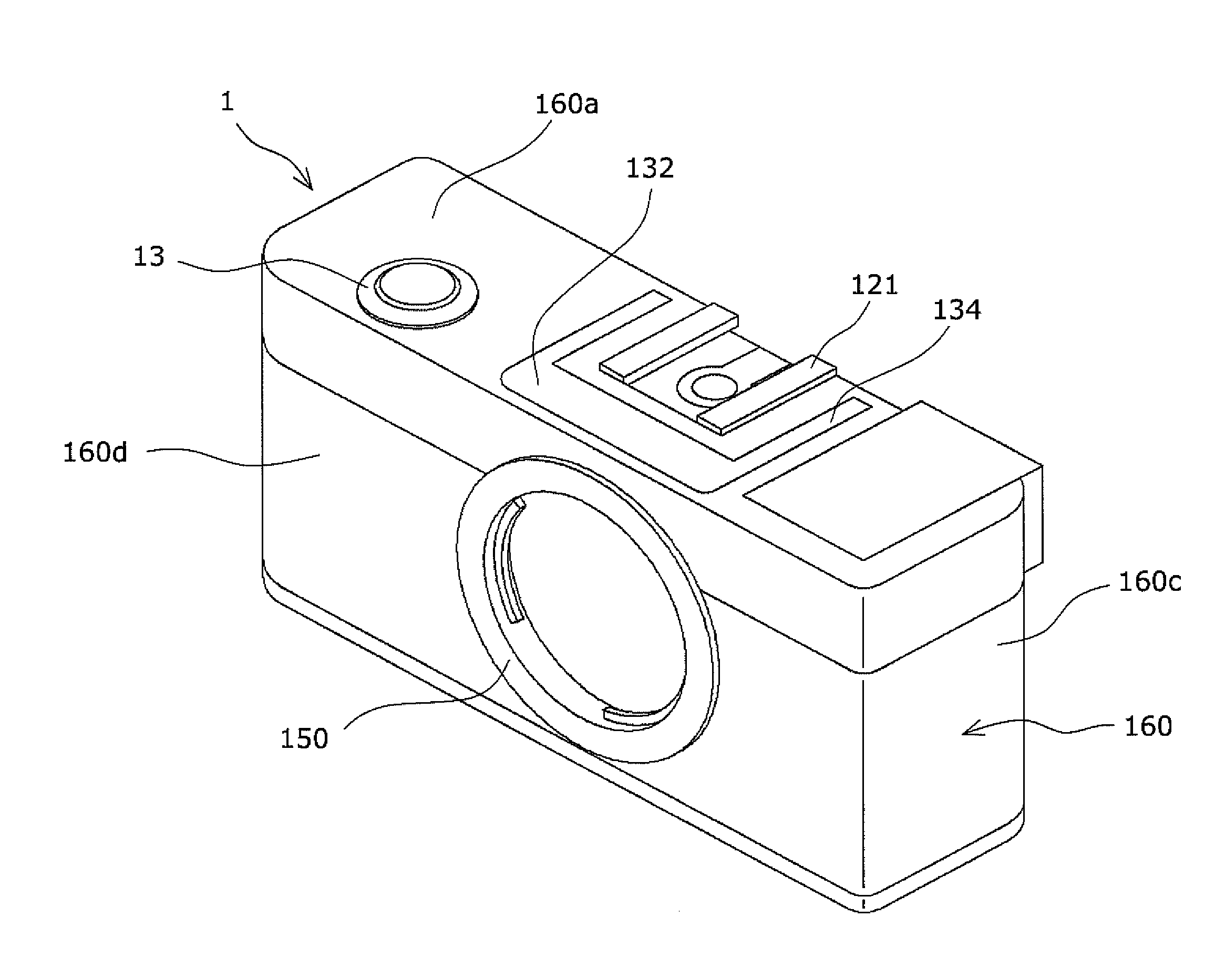
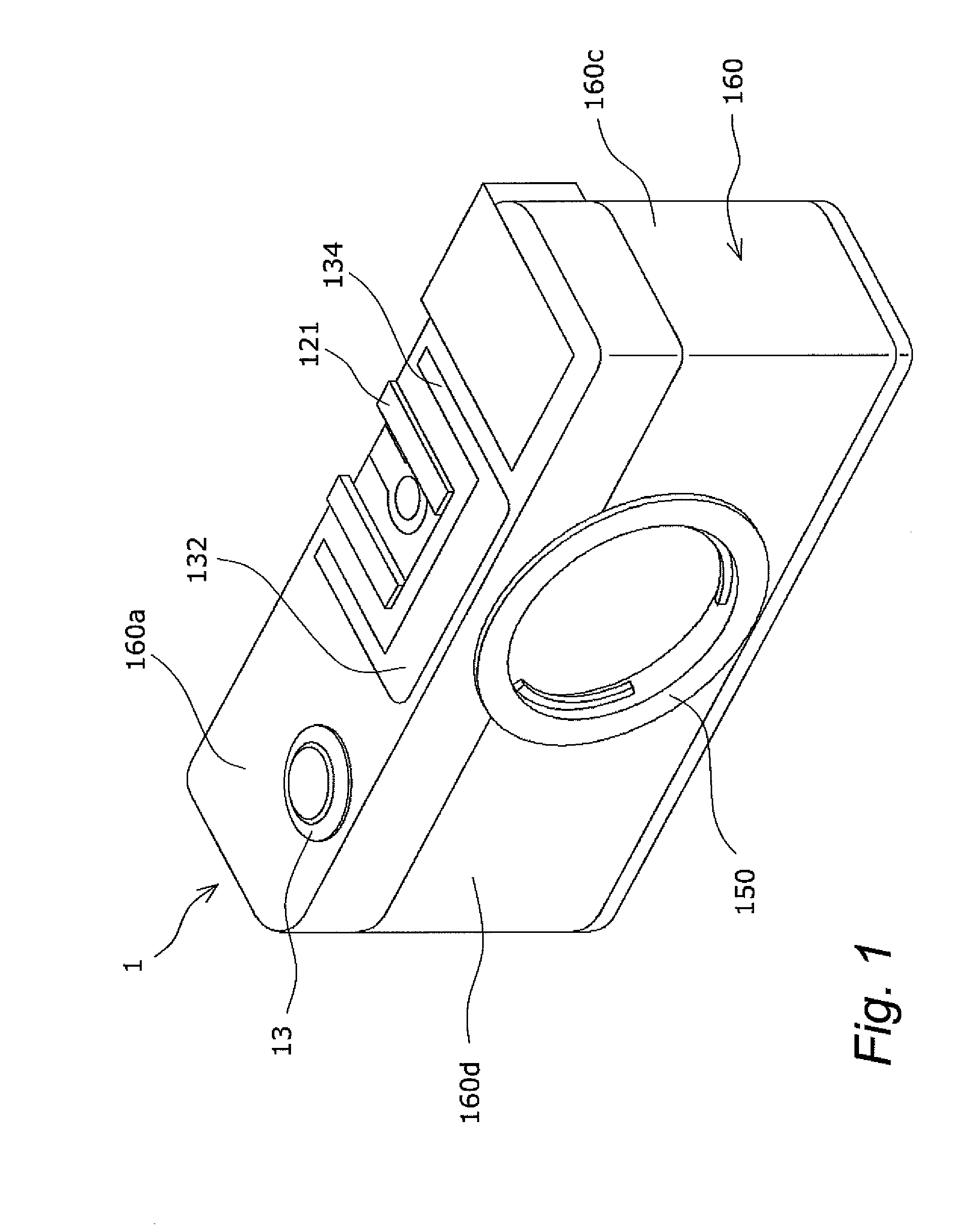
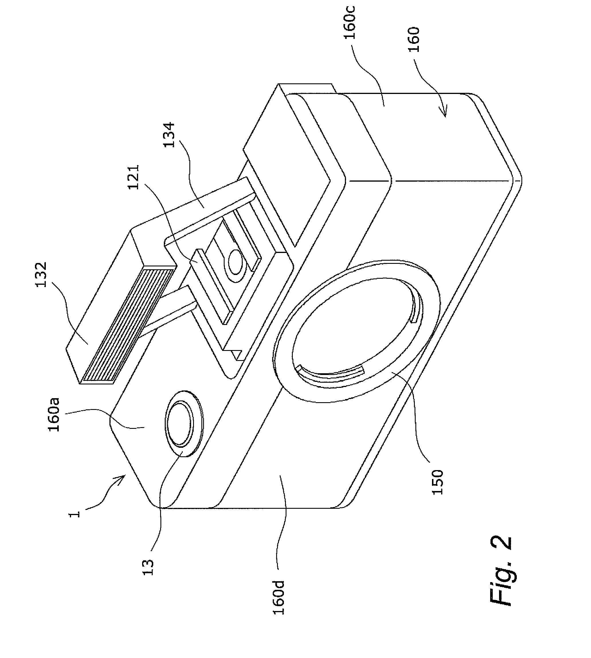
[0023]The digital camera according to this embodiment (an example of an imaging device) includes the camera body 1 and a lens unit.

1: Lens Unit

[0024]The lens unit (not shown) includes an optical system (not shown) that forms an optical image of a subject, a lens mount (not shown) having an electrical contact (not shown), and a lens controller (not shown). The lens mount is mounted to a body mount 150 (discussed below) of the camera body 1. The line AX in FIG. 3 indicates the optical axis center line of the optical system. The lens controller holds lens data related to the use of the lens unit and so forth, and lens data can be transferred through ...


PUM


Abstract

A camera body allows the mounting of a lens unit configured to form an optical image of a subject, and includes a body mount, an imaging element, a capacitor, and a housing member. The body mount allows a lens unit to be mounted. The imaging element includes a light receiving face arranged to receive light passing through the lens unit, and converts an optical image of the subject into an electrical signal. The capacitor is disposed above the imaging element and more to the imaging element side than the body mount in a landscape orientation. The housing member accommodates the imaging element and the capacitor.

Description

CROSS-REFERENCE TO RELATED APPLICATIONS[0001]This application claims priority to Japanese Patent Application No. 2008-232069 filed on Sep. 10, 2008. The entire disclosure of Japanese Patent Application No. 2008-232069 is hereby incorporated herein by reference.BACKGROUND[0002]1. Technical Field[0003]The technical field relates to a camera body to which a lens unit can be mounted, and to an imaging device equipped with this camera body.[0004]2. Description of the Related Art[0005]The single lens reflex camera discussed in Japanese Laid-Open Patent Application H10-39388 is a silver halide camera that makes use of silver halide film, and is equipped with a lens unit and a camera body. This camera body includes a film cartridge chamber, a spool chamber, a focal plane shutter, and a charge capacitor used for a flash. The cartridge chamber and the spool chamber are disposed on the left and right sides with the focal plane shutter in between. The spool chamber is equipped with a spool, and...

Claims


Application Information

Patent Timeline
IPC IPC(8): H04N5/225
CPCH04N5/2252H04N23/51
Inventor SHINTANI, DAI
Owner PANASONIC CORP
Why Eureka
Try Eureka