Back light unit and liquid crystal display using the same

a backlight unit and liquid crystal display technology, applied in the field of backlight units and liquid crystal displays, can solve the problems of extended installation time period and deterioration of production yield

Active Publication Date: 2010-03-11
LG DISPLAY CO LTD
View PDF6 Cites 7 Cited by
  • Summary
  • Abstract
  • Description
  • Claims
  • Application Information

AI Technical Summary

Benefits of technology

[0009]Accordingly, the present invention is directed to a backlight unit and liquid crystal display that substantially obviates one or more of the problems due to limitations and disadvantages of the related art.

Problems solved by technology

Conventionally, the optical film layer was supported by making a hole in the cover bottom and installing the guide, and because this was performed by a manual operation, as the quantity of the guides increases, there was a problem that an installation time period is extended and a production yield is deteriorated.
In a related art guide, due to installation restrictions or various factors, as a diffusion plate substantially supported by the guide is bent, a problem such as lattice mura occurs and thus improvement of the problem is requested.

Method used


Image

  • Back light unit and liquid crystal display using the same
  • Back light unit and liquid crystal display using the same
  • Back light unit and liquid crystal display using the same

Examples


Embodiment Construction

[0019]Reference will now be made in detail to embodiments of the present invention examples of which are illustrated in the accompanying drawings.

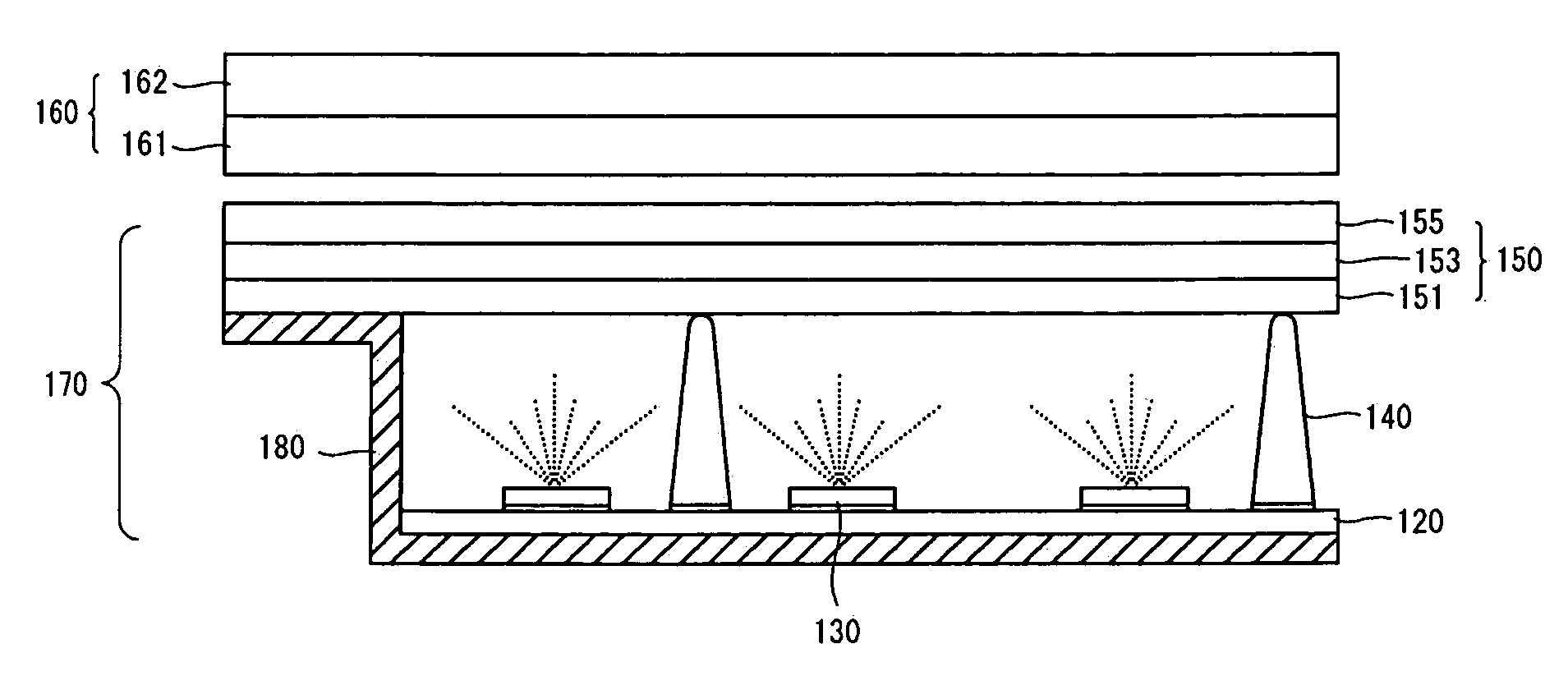
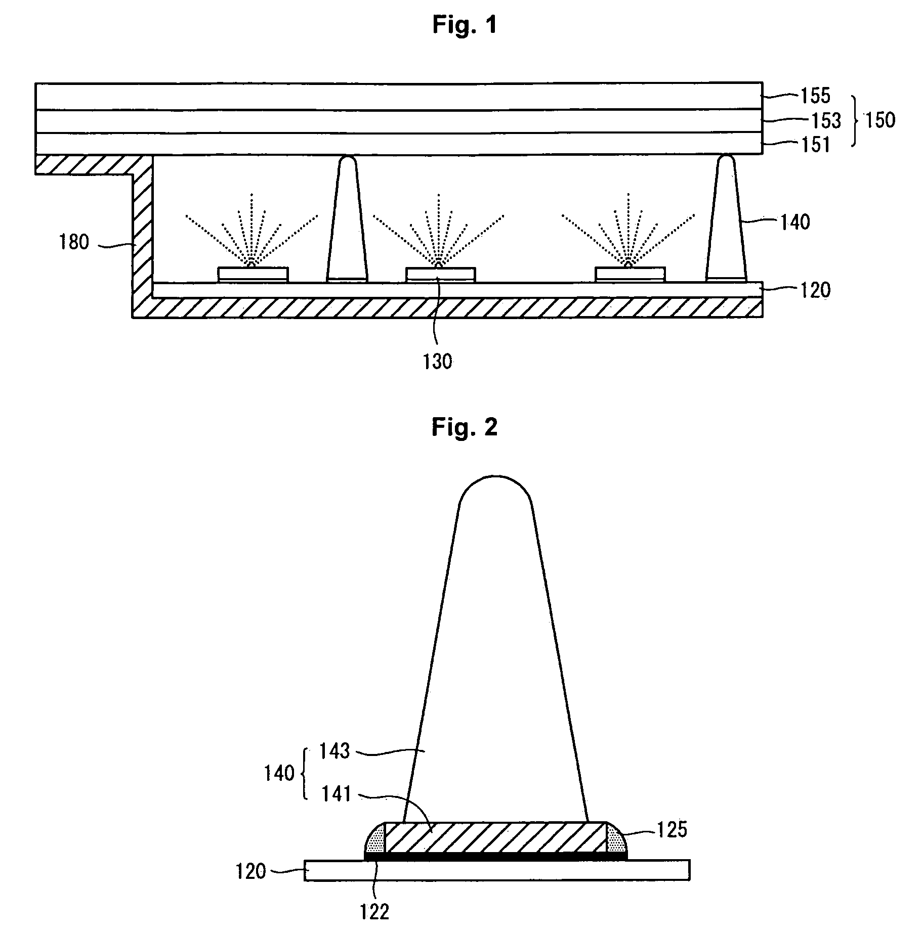
[0020]As shown in FIG. 1, a backlight unit according to an embodiment of this document includes a cover bottom 180. Further, the backlight unit includes a printed circuit board (PCB) 120 that is supported by the cover bottom 180. Further, the backlight unit includes a light emitting element 130 that is positioned on the PCB 120. Further, the backlight unit comprises an optical film layer 150 that is supported by the cover bottom 180 and that is positioned on the PCB 120. Further, the backlight unit comprises a guide 140 that is mounted separately from the light emitting element 130 on a surface of the PCB 120 in order to support the optical film layer 150.

[0021]The cover bottom 180 is made of a material having high durability and heat resistance. The cover bottom 180 may have steps corresponding to constituent elements in order to receive ...


PUM

PropertyMeasurementUnit
round conical shapeaaaaaaaaaa
flat conical shapeaaaaaaaaaa
conical shapeaaaaaaaaaa

Abstract

A backlight unit is provided. The backlight unit comprises: a cover bottom: a printed circuit board (PCB) that is supported by the cover bottom; a light emitting element that is positioned on the PCB; an optical film layer that is supported by the cover bottom and that is positioned on the PCB; and a guide that is mounted separately from the light emitting element in a surface of the PCB in order to support the optical film layer.

Description

[0001]This application claims the benefit of Korean Patent Application No. 10-2008-089235 filed on Sep. 10, 2008 which is hereby incorporated by reference for all purposes as if fully set forth herein.BACKGROUND[0002]1. Field of Invention[0003]This document relates to a backlight unit and a liquid crystal display using the same.[0004]2. Discussion of the Related Art[0005]As research in information-oriented technology develops, a market of a display device, which is a connection medium between a user and information increases. Accordingly, use of a flat panel display (FPD) such as a liquid crystal display (LCD), an organic light emitting diode (OLED), and a plasma display panel (PDP) increases. The LCD that can embody high resolution and that can increase a size as well as decrease a size is widely used.[0006]The LCD is classified as a light receiving display device. The LCD receives light from a backlight unit positioned at a lower part of a liquid crystal panel and expresses an ima...

Claims


Application Information

Patent Timeline
Patent Type & Authority Applications(United States)
IPC IPC(8): G02F1/13357
CPCG02F1/133608F21V15/04G02F1/1333G02F1/1335
Inventor LEE, YONGKONKIM, KISEONG
Owner LG DISPLAY CO LTD
Why Eureka
Try Eureka