Dynamic bandwidth allocating method and device with hardware reduced and bandwidth usability improved

a bandwidth allocation and hardware technology, applied in data switching networks, multiplex communication, star/tree networks, etc., can solve the problems of increasing or decreasing the amount of information, increasing the volume of hardware implementing the sharing of bandwidths, and hence increasing costs. , to achieve the effect of increasing bandwidth usability and reducing hardware volum

Inactive Publication Date: 2010-03-11
OKI ELECTRIC IND CO LTD
View PDF5 Cites 30 Cited by
  • Summary
  • Abstract
  • Description
  • Claims
  • Application Information

AI Technical Summary

Benefits of technology

[0018]According to the bandwidth allocating method and device of the present invention, there are attained advantages

Problems solved by technology

The amount of the information may increase or decrease, and possibly vanish.
However, there are prob

Method used


Image

  • Dynamic bandwidth allocating method and device with hardware reduced and bandwidth usability improved
  • Dynamic bandwidth allocating method and device with hardware reduced and bandwidth usability improved
  • Dynamic bandwidth allocating method and device with hardware reduced and bandwidth usability improved

Examples


third embodiment

[0069]The third embodiment is directed to a manner of using the subscriber unit and allocating bandwidths so as to improve the fairness or the bandwidth usability even when subscriber units have the lopsided amounts of communication traffic.

fourth embodiment

[0070]The fourth embodiment will be described below which is directed to a bandwidth allocating system adapted for three or more channels available.

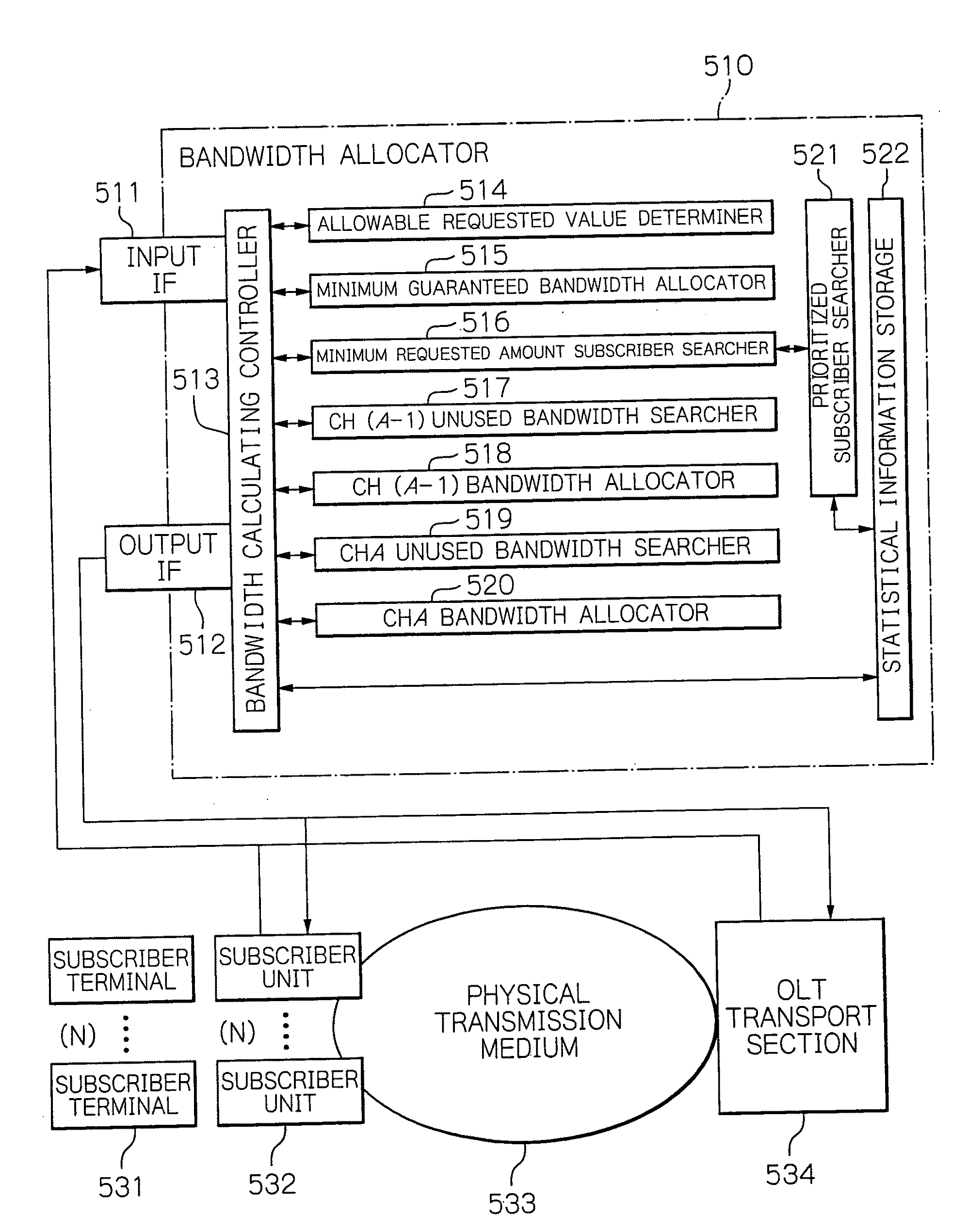
[0071]Now, the configuration of the first embodiment will be described below. FIG. 8 is a schematic block diagram showing the configuration of the bandwidth allocating section, or allocator, 510 in accordance with the first embodiment of the present invention. As shown in FIG. 8, the bandwidth allocator 510 includes an input interface 511, an output interface 512, a bandwidth calculating controller 513, an allowable requested value determiner (leaky bucket) 514, the minimum guaranteed bandwidth allocator 515, the minimum requested amount subscriber searcher 516, a ch(A−1) unused bandwidth searcher 517, a ch(A−1) bandwidth allocator 518, a chA unused bandwidth searcher 519, a chA bandwidth allocator 520, a prioritized subscriber searcher 521, and a statistical information storage 522. In order to facilitate understanding, FIG. 8 also illu...

first embodiment

[0073]The subscriber unit 532 shares the communication channels with other subscriber units 532. Therefore, if the subscriber unit 532 would freely select the communication channel, the available channels would collide against each other. Then, in respect of up-going and down-going communications, the bandwidth allocator 510 determines a period of time in which and a channel on which the subscriber unit 532, for example, ONU, and a station device, for example, OLT, have to transmit signals, and indicates the results from the determination to these devices, thereby preventing a collision. The first embodiment is directed to the case where the bandwidth allocator 510 is used in an optical access network. However, the bandwidth allocator 510 may similarly be used for a radio communication network, i.e. communication over air space rather than an optical fiber.

[0074]In operation, as the first step, the subscriber unit 532 sends bandwidth allocating or assigning calculation indexes (requ...


PUM


Abstract

In subscriber units 0 to (N−1), a subscriber unit to be allocated to a bandwidth is defined as a subscriber unit K, where K is an integer from 0 to (N−1) inclusive. In a bandwidth allocating method, a free bandwidth in a communication channel ch(K−1) not used by the subscriber unit (K−1) is found, and a bandwidth requested by the subscriber unit K is allocated to the free bandwidth in the communication channel ch(K−1). A free bandwidth in the communication channel chK is found on the basis of a residual bandwidth requested by the subscriber unit K not allocated to the bandwidth in the communication channel ch(K−1), and the residual bandwidth requested by the subscriber unit K is allocated to the found free bandwidth in the communication channel chK. The operation is repeated for the subscriber units 0 to (K−1) and (K+1) to (N−1).

Description

BACKGROUND OF THE INVENTION[0001]1. Field of the Invention[0002]The present invention relates to a method and a system for allocating bandwidths for use in a telecommunications network having available channels limitative, such as a wavelength division multiplex passive optical network (WDM-PON) and a code division multiplex access passive optical network (CDMA-PON).[0003]2. Description of the Background Art[0004]FIG. 1 is a schematic system diagram useful for understanding an exemplified allocation of bandwidths for communications between central-office (CO) equipment 10 and subscriber terminals, e.g. personal computers, through network devices for subscriber, i.e. subscriber units 11 to 14. In the system having bandwidths limitative which are available between the central-office equipment 10 and the subscriber units 11 to 14, as shown in FIG. 1, the subscriber units 11 to 14 are adapted to apply for a parameter, such as a bandwidth, for communication to the central-office equipmen...

Claims


Application Information

Patent Timeline
IPC IPC(8): H04L29/02H04L12/44
CPCH04L12/5695H04L47/829H04L45/28H04Q2011/0064H04L5/003H04Q11/0067H04L47/70
Inventor NAKAHIRA, YOSHIHIRO
Owner OKI ELECTRIC IND CO LTD
Why Eureka
Try Eureka