Camera body and imaging device equipped with same
- Summary
- Abstract
- Description
- Claims
- Application Information
AI Technical Summary
Benefits of technology
Problems solved by technology
Method used
Image
Examples
first embodiment
1-1: Overview of Digital Camera
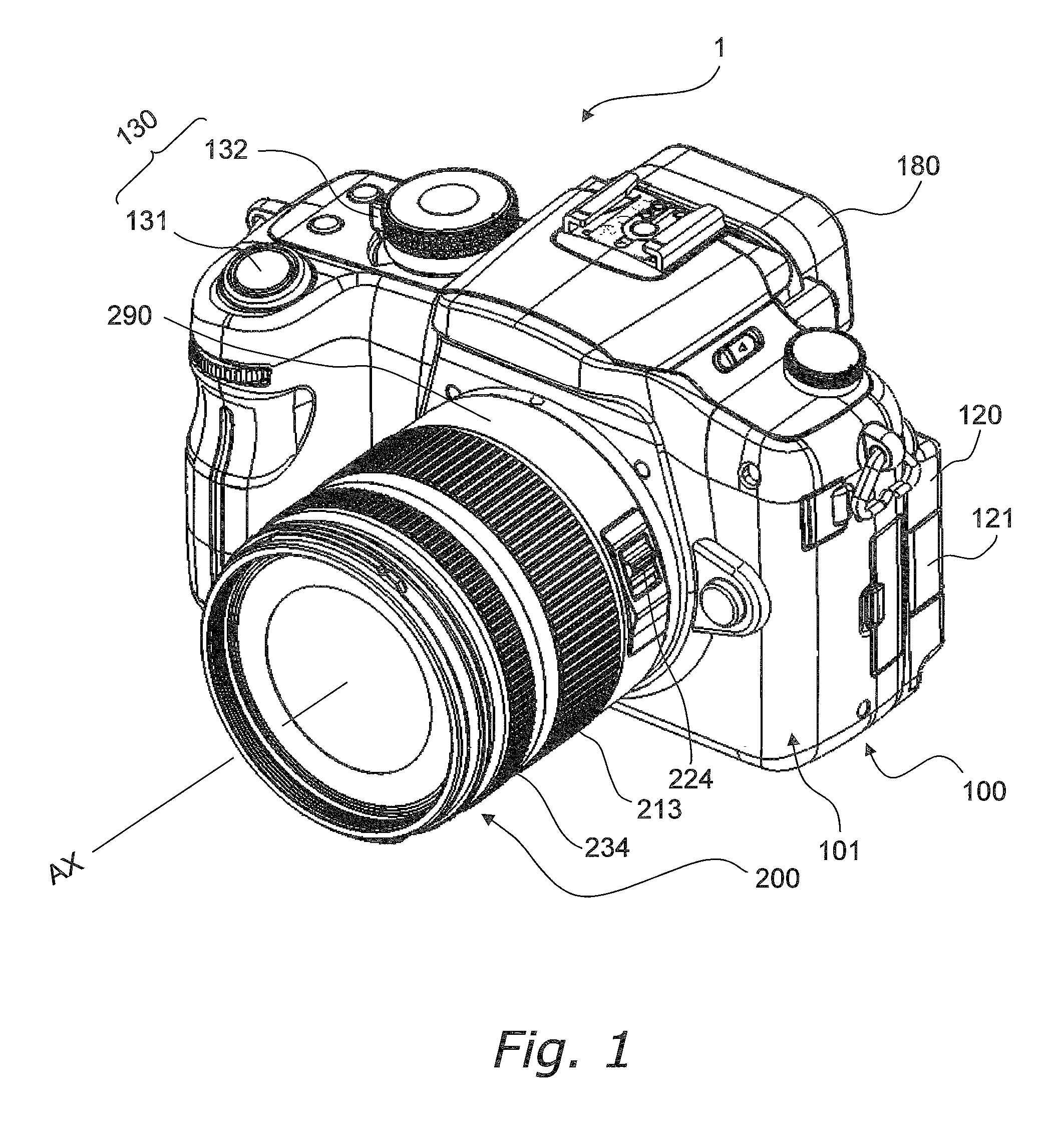
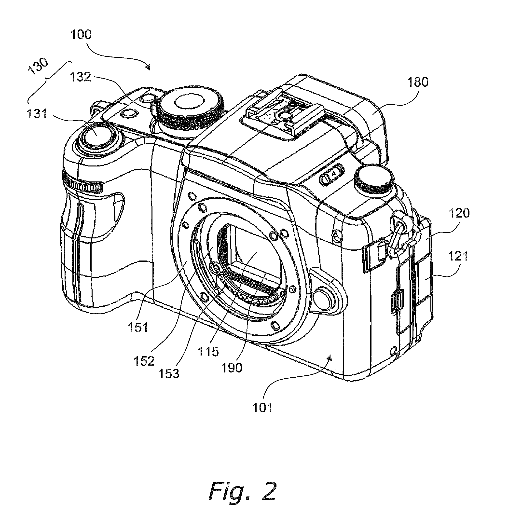
[0028]FIG. 1 is an oblique view of a digital camera 1 according to a first embodiment. FIG. 2 is an oblique view of a camera body 100. FIG. 3 is a function block diagram of the digital camera 1.
[0029]The digital camera 1 is an interchangeable lens digital camera, and includes the camera body 100 and a lens unit 200 that can be mounted to the camera body 100.
[0030]Unlike a single lens reflex camera, the camera body 100 does not have a mirror box device, so the flange back is smaller than with a single lens reflex camera. Also, reducing the size of the flange back makes the camera body 100 smaller. Furthermore, reducing the size of the flange back affords greater latitude in the design of the optical system, so the lens unit 200 can be smaller. The various components will now be described in detail.
[0031]For the sake of this description, the subject side of the digital camera 1 will also be called the front, the vertical upper side will also be called th...
second embodiment
[0123]In the first embodiment above, the heat radiating member 198 is connected to the diaphragm support 116, but the heat radiating member 198 may instead be connected to another member. Here, the description will focus on differences from the camera body 100 of the first embodiment, and portions that are shared will not be described again. Furthermore, members having substantially the same function as in the first embodiment will be numbered the same, and will not be described again in detail.
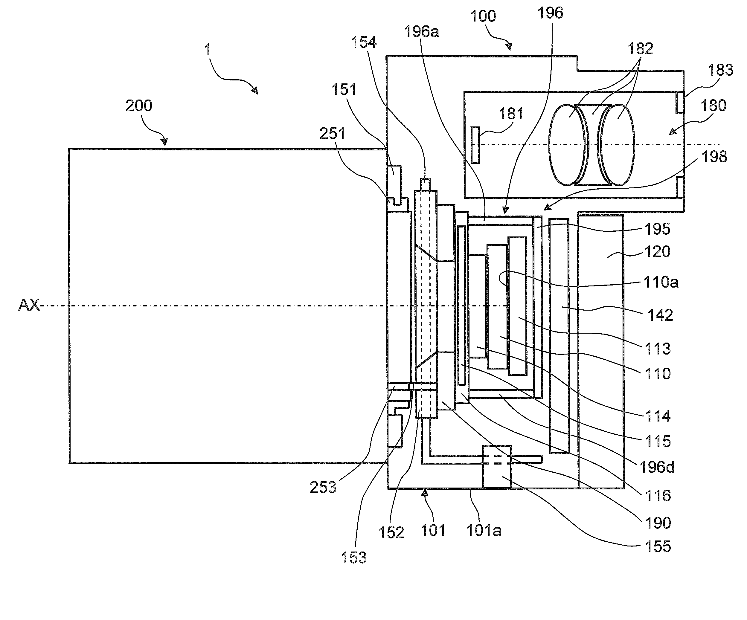
[0124]FIG. 9 is a simplified cross section of a camera body 400 according to the second embodiment. The camera body 400 differs from the camera body 100 in the first embodiment only in that the thermal conductor 196 of the heat radiating member 198 is connected not to the diaphragm support 116, but to the shutter unit 190, and the rest of the configuration is substantially the same as that of the camera body 100.
[0125]The thermal conductor 196 has a first plate 196a disposed above the CMOS im...
third embodiment
[0130]The embodiment described below is also conceivable. The description will focus on differences from the camera body 100 of the first embodiment, and portions that are shared will not be described again. Furthermore, members having substantially the same function as in the first embodiment will be numbered the same, and will not be described again in detail.
[0131]FIG. 10 is a simplified cross section of a camera body 500 according to the third embodiment. The camera body 500 differs from the camera body 100 in the first embodiment only in that the thermal conductor 196 of the heat radiating member 198 is connected not to the diaphragm support 116, but to the body mount contact support 152, and the rest of the configuration is substantially the same as that of the camera body 100.
[0132]The thermal conductor 196 has a first plate 196a disposed above the CMOS image sensor 110, a second plate 196b and a third plate 196c disposed to the sides of the CMOS image sensor 110, and a fourt...
PUM
 Abstract
Description
Claims
Application Information
 - R&D
- Intellectual Property
- Life Sciences
- Materials
- Tech Scout
- Unparalleled Data Quality
- Higher Quality Content
- 60% Fewer Hallucinations
Browse by: Latest US Patents, China's latest patents, Technical Efficacy Thesaurus, Application Domain, Technology Topic, Popular Technical Reports.
© 2025 PatSnap. All rights reserved.Legal|Privacy policy|Modern Slavery Act Transparency Statement|Sitemap|About US| Contact US: help@patsnap.com


