
Device for measuring the flow rate of ringer solution

a flow rate and flow rate technology, applied in volume metering, machines/engines, instruments, etc., can solve the problems of difficult to precisely adjust deterioration of precision, and medical accidents, etc., to achieve convenient manipulation, easy adjustment of the flow rate of ringer's solution, and small volume

Inactive Publication Date: 2010-03-11
LEE IN OK
View PDF2 Cites 3 Cited by
  • Summary
  • Abstract
  • Description
  • Claims
  • Application Information

AI Technical Summary

Benefits of technology

[0009]Therefore, the present invention has been made in view of the above-mentioned problems, and an object of the present invention is to provide a device for measuring the flow rate of Ringer's solution which can be conveniently carried and precisely measure the flow rate of Ringer's solution while obviating the need for installing a complicated measurement structure in a drip chamber.
[0011]Still another object of the present invention is to provide a device for measuring the flow rate of Ringer's solution which can measure the flow rate of Ringer's solution without using a costly measurement apparatus, and therefore can be widely distributed over hospitals and doctors' offices.
[0017]Thanks to the features of the present invention, the device can be manufactured to have a small volume so that the device can be conveniently manipulated with one hand, and the accurate flow rate of Ringer's solution can be outputted as a quantitative value so that a user can easily adjust the flow rate of Ringer's solution with the other hand.

Problems solved by technology

However, in this procedure for adjusting the flow rate of the Ringer's solution, since the procedure is implemented depending upon the user's eyes based on experience, it is difficult to precisely adjust the flow rate of Ringer's solution.
In this regard, because the adjustment procedure cannot precisely adjust the flow rate of Ringer's solution, a medical accident is likely to occur.
In this regard, prior arts are disclosed in Korean Unexamined Patent Publication No. 2004-0048889 entitled “Volumetric flow measurement device for intravenous injection set” and Korean Unexamined Patent Publication No. 2005-0039780 entitled “A system for measuring the flow rate of Ringer's solution using a method of image signal processing.” Nevertheless, in these prior arts, since a drip in a drip chamber is sensed using infrared rays and the number of drips and the quantitative amount of Ringer's solution are determined, a precision can be deteriorated due to the influence by outside light, and when installing the device or system for measuring the flow rate of Ringer's solution, inconvenience is caused and a substantial cost is required.
Due to these facts, the device or system could not be actually employed on a commercial scale.
Nonetheless, this system suffers from defects in that the structure of a drip chamber should be changed and the system cannot be practically used due to the complexity of the drip chamber and the system.
Further, because the prior arts basically adopt a process of measuring a volume by a sensor, they cannot help but adjust the flow rate of Ringer's solution by entirely relying on the operation of the measurement device or system.
That is to say, because the measurement device or systems according to the prior arts cannot be practically used due to the problems described above, it is the norm in a hospital or a doctor's office for a nurse to measure the time during which a predetermined number of drips drip, using a watch having a second hand, and to calculate the flow rate of Ringer's solution.
In this procedure, since it is necessary to alternately look at the watch and a drip chamber, an error is likely to be caused in the calculated flow rate.

Method used


Image

  • Device for measuring the flow rate of ringer solution
  • Device for measuring the flow rate of ringer solution
  • Device for measuring the flow rate of ringer solution

Examples


Embodiment Construction

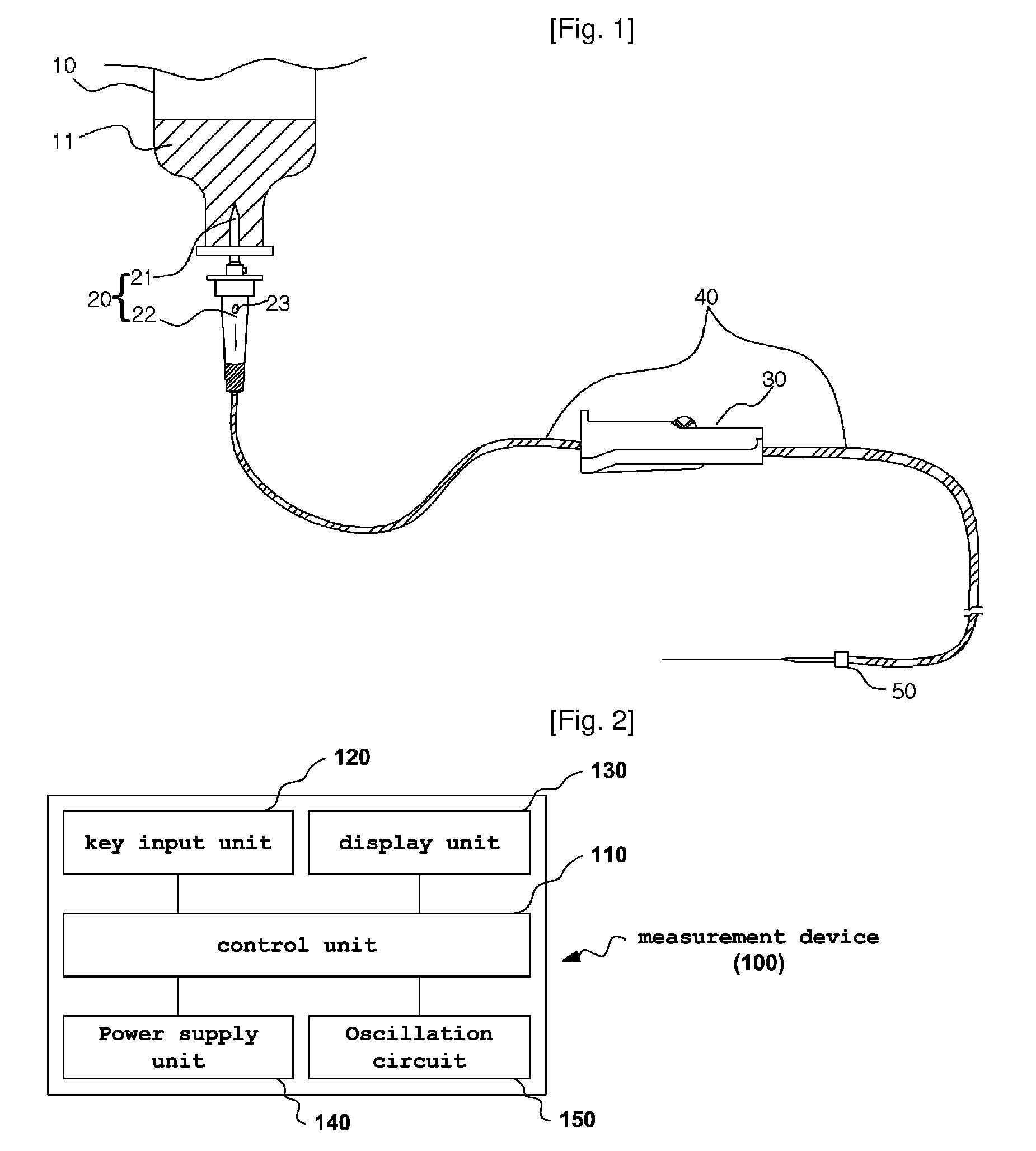
[0030]FIG. 2 is a view illustrating the construction of a device 100 for measuring the flow rate of Ringer's solution in accordance with an embodiment of the present invention.

[0031]Referring to FIG. 2, the device 100 for measuring the flow rate of Ringer's solution according to the present invention includes a key input unit 120 for permitting a key input from a user, a power supply unit 140 for supplying power to the respective component parts of the device 100 for measuring the flow rate of Ringer's solution, an oscillation circuit 150 for oscillating a signal having a preset frequency, a display unit 130 for outputting the calculated flow rate of Ringer's solution as a quantitative value, and a control unit 110 for controlling the operations of these sections and circuits 120, 130, 140 and 150.

[0032]In detail, the key input unit 120 has a number input key which is provided to allow the user to input a number signal each time when the drip 23 drops in the drip chamber 22, a reset...


PUM


Abstract

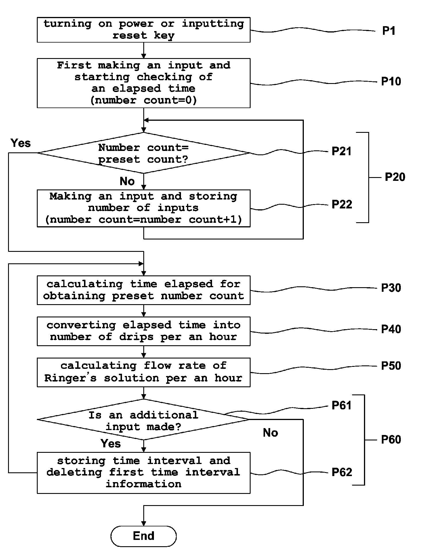
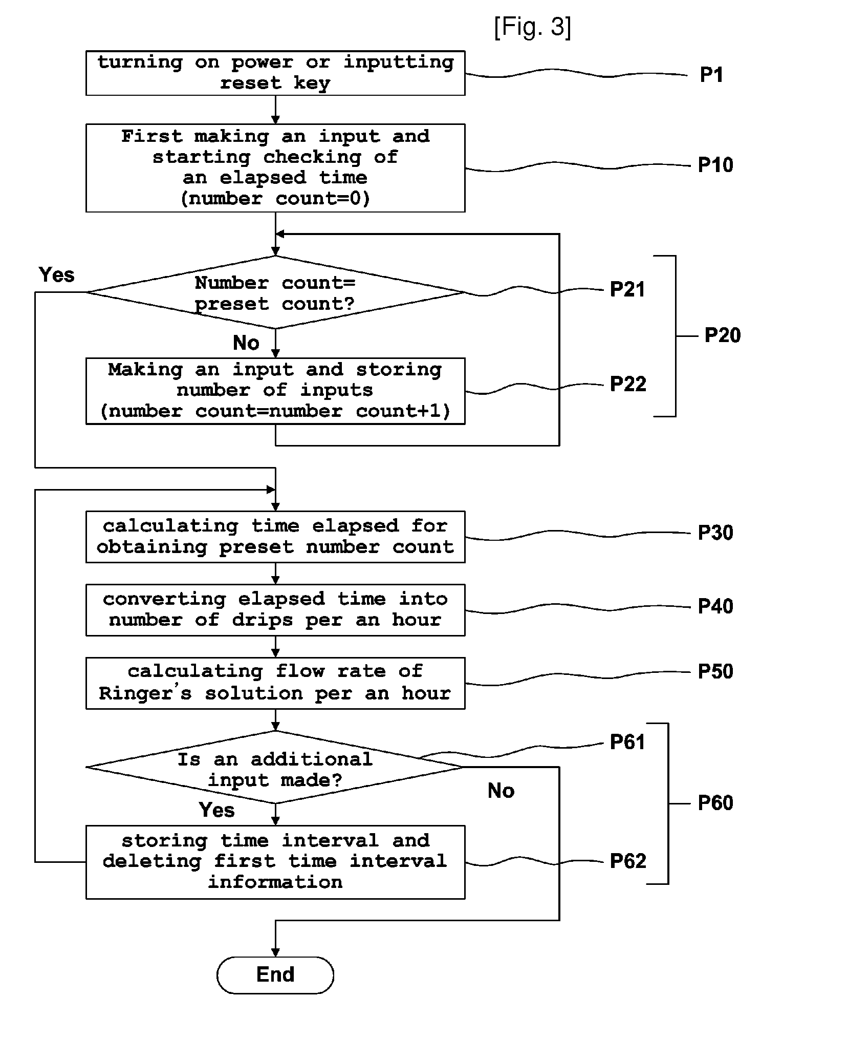
A device for measuring a flow rate of Ringer's solution includes a key input unit including a number input key through which a user can make an input each time when a drip drips in a drip chamber; a power supply unit for supplying power; an oscillation circuit for oscillating a signal having a preset frequency; a display unit for quantitatively outputting a calculated flow rate of Ringer's solution; and a control unit for calculating an elapsed time when the input is made through the number input key of the key input unit for a preset number of times, calculating the number of drips per an hour using the preset number of times and the calculated elapsed time, acquiring a quantitative flow rate of Ringer's solution by multiplying a preset volume of each drip and the calculated number of drips, and outputting the acquired flow rate to the display unit.

Description

TECHNICAL FIELD[0001]The present invention relates to a device for measuring the flow rate of Ringer's solution, and more particularly to a portable device for measuring the flow rate of Ringer's solution, which can measure, as a quantitative rate, the amount of Ringer's solution flowing through an intravenous injection needle.BACKGROUND ART[0002]Referring to FIG. 1, as is generally known in the art, an intravenous injection system for directly injecting medicine into a vein includes a bottle 10 containing Ringer's solution 11, a dripper 20 composed of an insertion needle 21 which is inserted through a closure lid provided to the bottle 10 and allows the Ringer's solution 11 to flow therethrough and a drip chamber 22 which is formed to allow the Ringer's solution 11 to drop in the shape of a drip 23 therein, an injection needle 50 to be inserted into the vein, a tube 40 connecting the dripper 20 and the injection needle 50 with each other and allowing the Ringer's solution 11 to flo...

Claims


Application Information

Patent Timeline
IPC IPC(8): G06F19/00A61M37/00G01F1/00
CPCA61M5/1689G01F13/006A61M2205/583A61M5/168
Inventor LEE, DOO YONG
Owner LEE IN OK
Learn More