Method of manufacturing stator for dynamoelectric machine

a technology of dynamoelectric machines and stators, which is applied in the manufacture of dynamoelectric machines, dynamo-electric machines, magnetic bodies, etc., can solve the problems of large compression forces on coil end parts, difficult to realize a suitable magnetic circuit of the stator, and difficult to mount the hollow cylindrical electric wire assembly to the stator core, etc., to achieve the effect of reducing the axial height of the connecting portions and reducing the axial height of each connecting portions

Active Publication Date: 2010-03-18
DENSO CORP
View PDF4 Cites 10 Cited by
  • Summary
  • Abstract
  • Description
  • Claims
  • Application Information

AI Technical Summary

Benefits of technology

[0019]With the above method, it is possible to mount the hollow cylindrical electric wire assembly to the stator core which has a unitary (or one-piece) structure. Consequently, compared to the case of employing the divided stator core structure as disclosed in Japanese Patent First Publication No. 2002-51485, it is possible to realize a more suitable magnetic circuit of the stator, thereby improving the performance of the dynamoelectric machine. Moreover, it is unnecessary to shrinkage-fit a hollow cylindrical case onto the radially outer surface of the stator core as in the case of employing the divided stator core structure. Furthermore, with the above method, it is possible to minimize the air gaps between the shaped electric wires in the assembling and rolling steps. Consequently, the size of the stator coil (i.e., the hollow cylindrical electric wire assembly) can be minimized, and the performance of the stator can be improved.
[0021]In the mounting step, with the radial expansion of the hollow cylindrical electric wire assembly, the circumferential spaces between adjacent pairs of the straight stacked portions are increased and the axial heights of the connecting portions are decreased.

Problems solved by technology

However, when the stator core has a unitary (or one-piece) structure, it is very difficult to mount the hollow cylindrical electric wire assembly to the stator core.
However, with the divided stator core structure, it would be difficult to realize a suitable magnetic circuit of the stator.
Therefore, it is necessary to apply large compression forces to the coil end parts.
However, this will cause the coil end parts to be greatly deformed, thereby increasing the air gaps between the shaped electric wires making up the stator winding set.

Method used


Image

  • Method of manufacturing stator for dynamoelectric machine
  • Method of manufacturing stator for dynamoelectric machine
  • Method of manufacturing stator for dynamoelectric machine

Examples


first embodiment

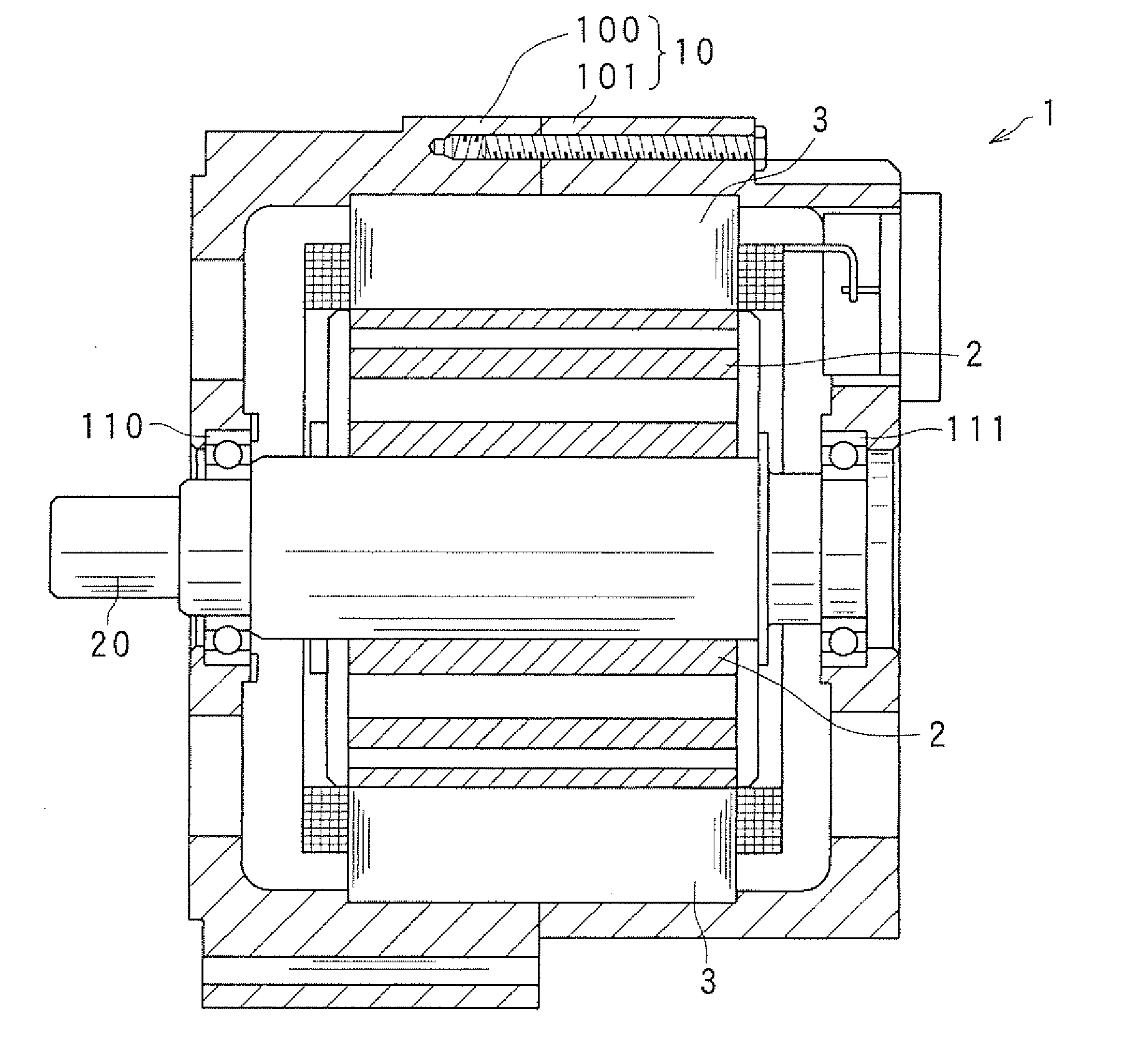
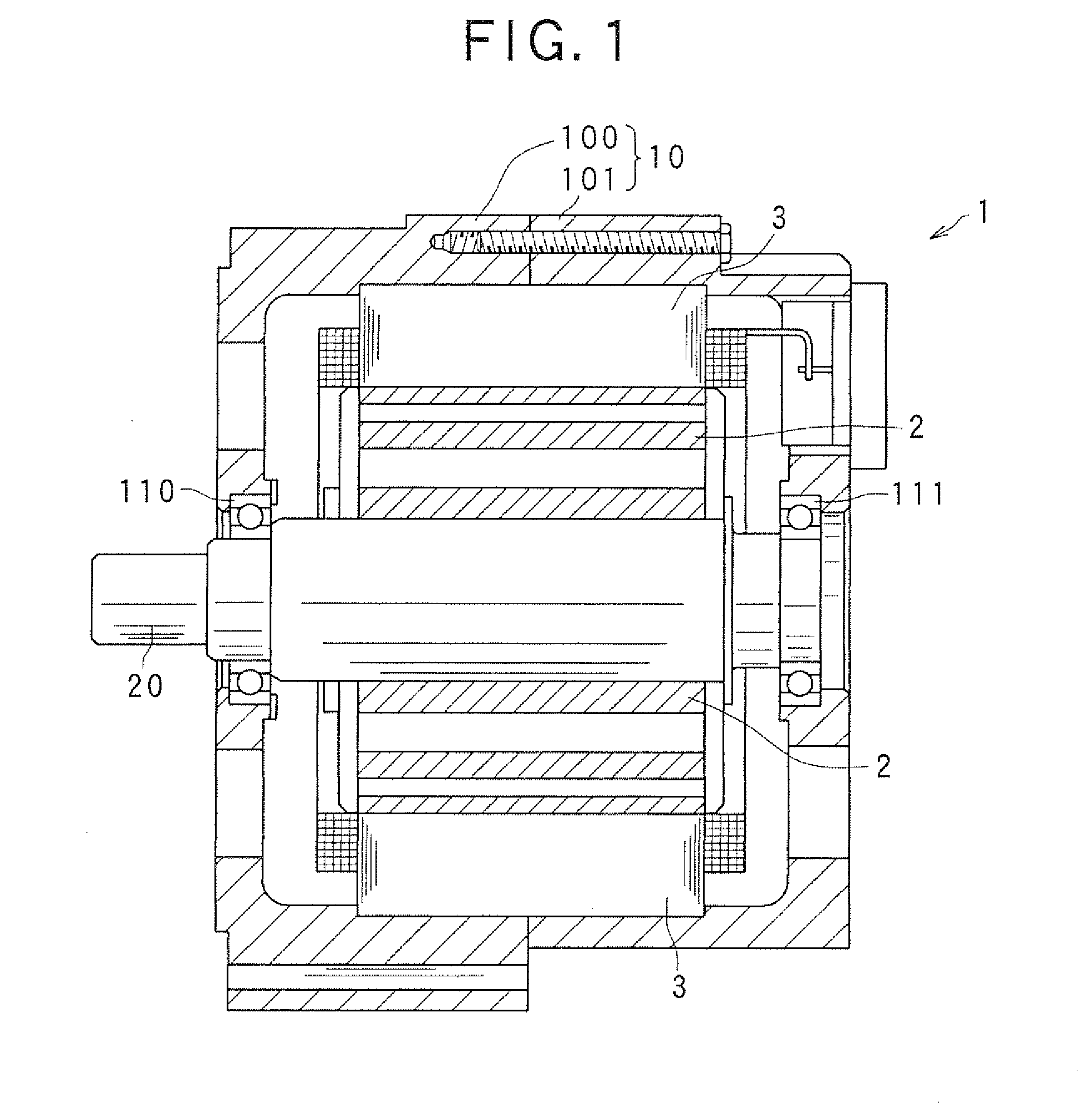
[0045]FIG. 1 shows the overall configuration of a dynamoelectric machine 1 which includes a stator 3 manufactured by a method according to the present embodiment.

[0046]The dynamoelectric machine 1 is configured to function as either an electric generator or an electric motor in a motor vehicle, such as an electric vehicle or a hybrid vehicle.

[0047]As shown in FIG. 1, the dynamoelectric machine 1 includes a housing 10 and a rotor 2 in addition to the stator 3. The housing 10 is composed of a pair of cup-shaped housing pieces 100 and 101 which are jointed together at the open ends thereof. The housing 10 has a pair of bearings 110 and 111 mounted therein, via which a rotating shaft 20 is rotatably supported by the housing 10. The rotor 2 is received in the housing 10 and fixed on the rotating shaft 20. The stator 3 is fixed in the housing 10 so as to surround the radially outer periphery of the rotor 2.

[0048]The rotor 2 includes a permanent magnet that is provided on a radially outer ...

second embodiment

[0104]In this embodiment, the hollow cylindrical electric wire assembly 48 is radially expanded using an expanding jig 521 which is different from the expanding jig 52 used in the first embodiment.

[0105]FIG. 14A illustrates the positioning of the expanding jig 521 with respect to the stator core 30. FIG. 14B illustrates the expanding jig 521 put into operation.

[0106]As seen from FIGS. 14A and 14B, the expanding jig 521 includes a small-diameter end 531 having a diameter smaller than the inner diameter of the hollow cylindrical electric wire assembly 48, a large-diameter portion 541 having a diameter substantially equal to the inner diameter of the stator core 30, a taper portion 551 that tapers from the large-diameter portion 541 to the small-diameter end 531, and a plurality of rollers 561 provided at the boundary between the large-diameter portion 541 and the taper portion 551. The rollers 561 are configured to be rollable in the axial direction of the expanding jig 521 (i.e., in ...


PUM

PropertyMeasurementUnit
interior anglesaaaaaaaaaa
shapeaaaaaaaaaa
outer diameteraaaaaaaaaa

Abstract

There is disclosed a method of manufacturing a stator for a dynamoelectric machine. The method includes a step of mounting a hollow cylindrical electric wire assembly, which includes a plurality of straight stacked portions of shaped electric wires, to a hollow cylindrical stator core that includes a plurality of slots formed in the radially inner surface thereof. The mounting step includes: (1) placing the electric wire assembly radially inside of the stator core so that each of the straight stacked portions of the electric wire assembly is radially aligned with a corresponding one of the slots of the stator core; and (2) radially expanding the electric wire assembly to insert the straight stacked portions of the electric wire assembly into the corresponding slots of the stator core.

Description

CROSS-REFERENCE TO RELATED APPLICATIONS[0001]This application is based on and claims priority from Japanese Patent Applications No. 2008-236941, filed on Sep. 16, 2008, and No. 2009-156936, filed on Jul. 1, 2009, the contents of which are hereby incorporated by reference into this application.BACKGROUND OF THE INVENTION[0002]1. Technical Field of the Invention[0003]The present invention relates generally to methods of manufacturing stators for dynamoelectric machines. More particularly, the invention relates to a method of manufacturing a stator for a dynamoelectric machine, which is characterized by a process of mounting a stator coil to a stator core that has a unitary structure.[0004]2. Description of the Related Art[0005]In recent years, dynamoelectric machines, such as electric motors and electric generators, have been required to be compact, be able to output high power, and have high quality.[0006]In particular, for dynamoelectric machines for use in motor vehicles, the space...

Claims


Application Information

Patent Timeline
Patent Type & Authority Applications(United States)
IPC IPC(8): H02K15/085
CPCH02K15/0025H02K15/0421Y10T29/49073Y10T29/49009H02K15/064
Inventor TAKADA, MASAHIROISHIZUKA, ATSUO
Owner DENSO CORP
Why Eureka
Try Eureka