

Methods and materials for zonal isolation
a technology of materials and zones, applied in the direction of sealing/packing, chemistry apparatus and processes, borehole/well accessories, etc., to achieve the effect of improving zonal isolation and alleviating cracks
Active Publication Date: 2010-03-18
SCHLUMBERGER TECH CORP
View PDF10 Cites 19 Cited by
- Summary
- Abstract
- Description
- Claims
- Application Information
AI Technical Summary
Benefits of technology
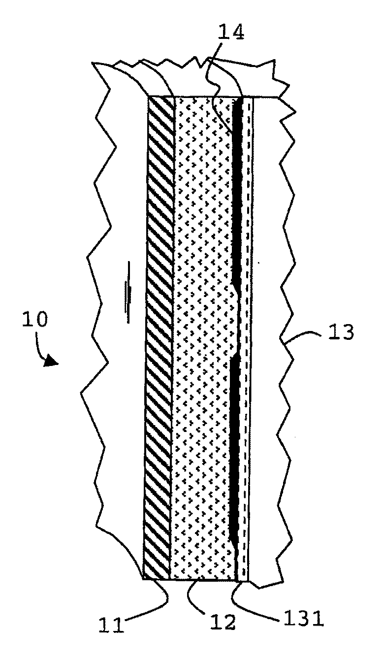
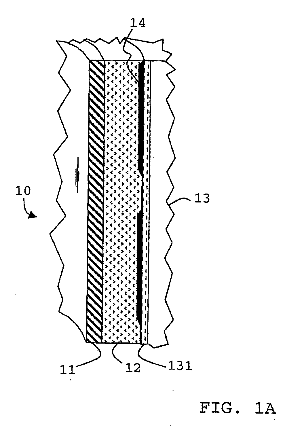
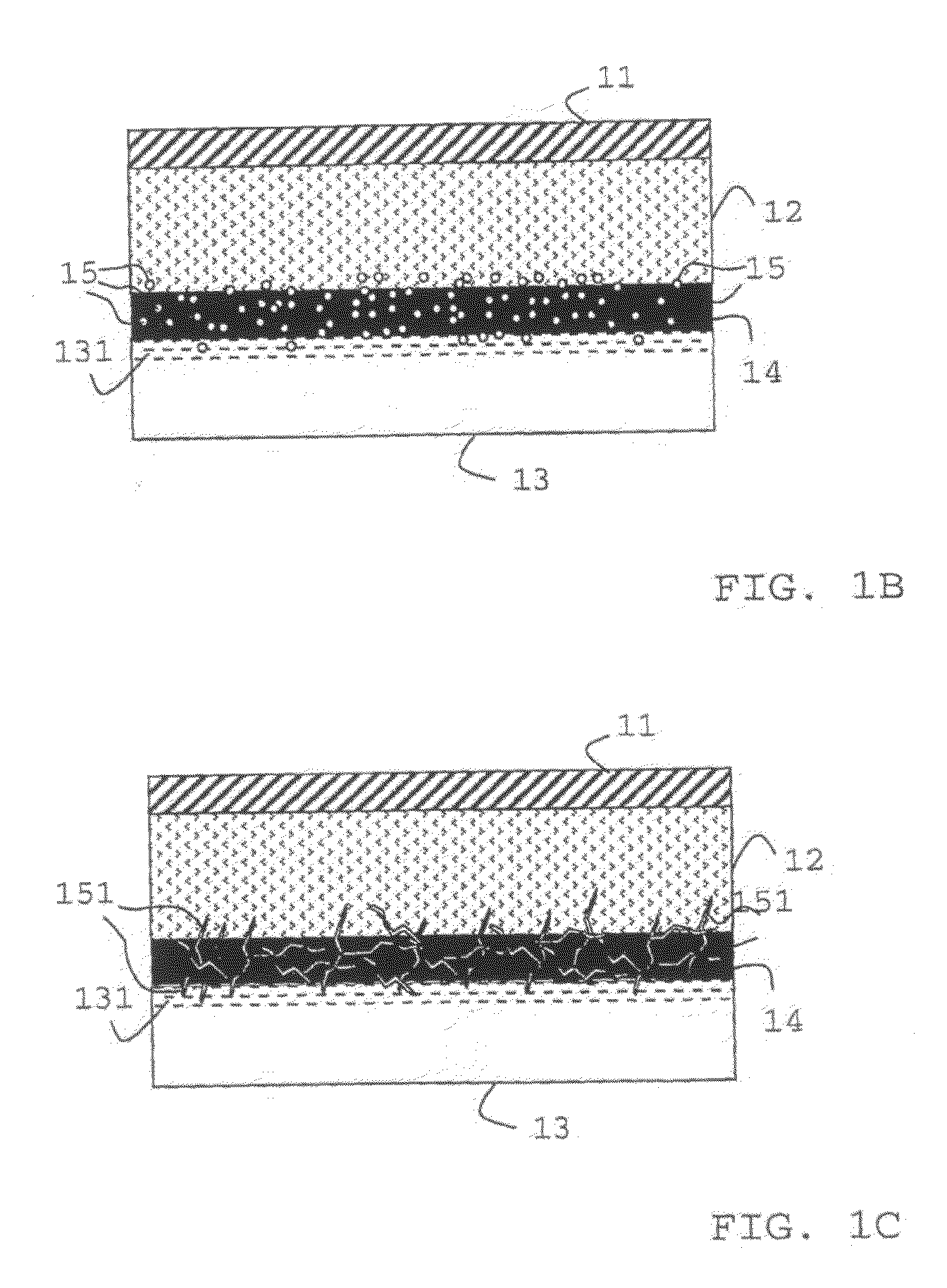
[0015]The invention relates to the use of one or more water-soluble reactive liquid components capable of subsequent polymerization or cross-linking to form a solid or layers of solid material to improve the zonal isolation and alleviate the impacts of cracks and fissures in the cement sheath around a completed subterranean well. The invention includes the steps of injecting a wellbore fluid carrying the reactive component or additive into the wellbore, injecting a cementitious composition as slurry into the wellbore and letting said reactive liquid component pass through at least one of the interfaces between cement and formation, cement and filter cake, and filter cake and formation before forming a solid of said reactive liquid component that traverses said at least one of the interfaces.
[0020]The use of surfactants in any of the wellbore fluid, the drilling fluid and / or the cements slurry can further improve several processes after placement including the wetting, the migration and the distribution of the reactive component. The beneficial effect of the surfactants can be enhanced if they contribute to the polymerization or cross-linking by providing for example at least one double bond capable of entering into the polymerization or cross-linking reaction of the reactive liquid component.
[0021]The methods and compositions of the present invention can be further improved through the use of an activator, initiator, catalyst, vulcanizing agent or accelerator in the wellbore fluid to promote polymerization or cross-linking. The polymerization or cross-linking may be further enhanced through heating from either natural sources, i.e., the reservoir temperature or by placing an artificial heat source inside the casing to heat the annulus of the wellbore from within.
Problems solved by technology
These interfaces are believed to contribute to observed zonal isolation problems, leaks and crossflow between zones.
Method used
View moreImage
Smart ImageViewing Examples

Examples
examples
Drilling Fluid Formulation Per Barrel (Metric Units)
[0087]0.59 barrel (94 l) Water
3.0 lbs (1.36 kg) Emulsifier (monooleate ester of polyethylene glycol MW 600)
0.32 barrel (51 l) Reactive liquid (1,2 polybutadiene oligomer (B1000 of Nippon Soda Co., MW 1160)
0.6 lbs (0.273 kg) Xanthan gum
[0088]2.0 lbs (0.91 kg) Fluid loss control agent (Drispac® Superlo a polyanionic cellulose by Drilling Specialities Inc)
100 lbs (45.5 kg) Barite
[0089]pH adjusted to pH 9 with NaOH.
Cement Formulation Per Barrel [Alternatively Per 600 ml]
4.6sk[802 g] Cement Dyckerhoff Class G4.3gal / sk[269 g] Water0.9gal / sk [54 g] PBD0.4%BWOC [3 g] TWEEN800.4%BWOC [3 g] potassium persulfate0.06gal / sk [5 g] Dispersant
Login to View More PUM
| Property | Measurement | Unit |
|---|---|---|
| melting point | aaaaa | aaaaa |
| melting point | aaaaa | aaaaa |
| Hydrophile Lipophile Balance | aaaaa | aaaaa |
Abstract
The invention relates to the use of one or more water-soluble reactive liquid component capable of subsequent polymerization or cross-linking to form a solid to improve the zonal isolation and alleviate the impacts of cracks and fissures in the cement sheath around a completed subterranean well. It includes the steps of injecting a wellbore fluid carrying the reactive component or additive into the wellbore, injecting a cementitious composition as slurry into the wellbore and letting said reactive liquid component pass through at least one of the interfaces between cement and formation, cement and filter cake, and filter cake and formation before forming a solid of said reactive liquid component that traverses said at least one of the interfaces.
Description
[0001]This invention relates to processes and materials to improve zonal isolation by using reactive materials in the well drilling and / or completion process.BACKGROUND OF THE INVENTION[0002]Drilling operations typically involve mounting a drill bit on the lower end of a drill pipe or drill stem and rotating the drill bit against the bottom of the hole to penetrate the formation, creating a borehole. A drilling fluid, typically referred to as drilling mud may be circulated down through the drill pipe, out the drill bit, and back up to the surface through the annulus between the drill pipe and the annular wall. The drilling fluid has a number of purposes including cooling and lubricating the bit, carrying the cuttings from the hole to the surface, and exerting a hydrostatic pressure against the borehole wall to prevent the flow of fluids from the surrounding formation into the borehole.[0003]A drilling fluid can place undesirable mechanical stress on the rock around the wellbore and ...
Claims
Login to View More Application Information
Patent Timeline
 Patent Type & AuthorityApplications(United States)
IPC IPC(8): E21B33/13C04B28/04C04B40/06C09K8/16C09K8/22C09K8/24C09K8/46
CPCC04B28/04C04B40/0633C04B2103/0035C04B2103/0046C09K8/46C09K8/16C09K8/22C09K8/24C04B2103/0067C04B24/08C04B24/2641C04B24/2676C04B2103/0053C04B2103/0055C04B2103/40C09K8/42C09K8/467C09K8/50C09K8/508C09K8/512E21B33/13E21B33/138E21B33/14
InventorSAWDON, CHRISTOPHER ALANLADVA, HEMANT KUMAR JETHALALJONES, TIMOTHY GARETH JOHNTUSTIN, GARY JOHN
OwnerSCHLUMBERGER TECH CORP