Contacts and connector

a technology of contact and connector, which is applied in the manufacture of contact parts, cell components, coupling device connections, etc., can solve the problems of shortening the life of connectors, limiting the height reduction in order to secure the fitting length, and affecting the reliability of conductive contacts, etc., to achieve reliable conductive contacts

Active Publication Date: 2010-03-18
ORMON CORP
View PDF5 Cites 4 Cited by
  • Summary
  • Abstract
  • Description
  • Claims
  • Application Information

AI Technical Summary

Benefits of technology

[0012]With this construction, since the contact, which is extended long in the direction roughly perpendicular to the voltage application direction, is formed by electroforming, an extra structure such as a bend is not required in the direction in which the contact portion is brought into sliding contact with the conductive member (fitting direction), so that it is possible to reduce the dimension in the fitting direction.
[0014]With this construction, since the spring portion, which is extended roughly perpendicular to the voltage application direction, which coincides with the direction in which the contact portion is brought into sliding contact with the conductive member, is formed by electroforming, the spring portion is shorter in the direction in which the spring portion is brought into sliding contact with the conductive member. Further, by changing a cavity width of a mold for electroforming, a thickness of the spring portion is changed, so that the contact portion can be press-contacted with the conductive member with desired elasticity. Therefore, the contact according to one or more embodiments of the present invention can be shortened in the fitting direction while securing the fitting length and the press-contacting force sufficient for the conductive contact.
[0015]In the contact according to one or more embodiments of the present invention, the spring portion is curved in the voltage application direction, whereby the height at which the contact portion is retained in the voltage application direction in the electroforming is made different from the height at which the retention portion is retained, so that the sliding contact distance of the contact portion with respect to the conductive member can be increased.
[0016]In the contact according to one or more embodiments of the present invention, if an electrode portion connected to a circuit is extended from the retention portion to an opposite side of the spring portion, the contact can be easily incorporated into the circuit.
[0020]With this construction, it is possible to provide a height-reduced connector having a small dimension in the fitting direction.
[0021]According to one or more embodiments of the present invention, the contact is formed by electroforming by applying a voltage in the direction of sliding contact with the conductive member. The contact is formed so as to be elastically deformable such that the respective portions of the contact are moved in the plane perpendicular to the voltage application direction in electroforming, whereby small-size contacts and a connector, which can achieve a reliable conductive contact, can be provided.

Problems solved by technology

As described in Patent Documents 1 and 2, in a case where contacts are formed by bending a metal plate, a radius dimension for bending is required, so that there is a limitation in reducing the height in order to secure the fitting length.
However, residual stresses or lattice defects occur due to the press working, so that the connector has a shorter lifetime, and variations in thickness become large on a product-to-product basis.
In addition, since the contacts used for such small-type connectors are extremely small, forming them by machining is not realistic.Patent Document 1: Japanese Laid-Open Patent Application No. 2004-55436

Method used


Image

  • Contacts and connector
  • Contacts and connector
  • Contacts and connector

Examples


Embodiment Construction

[0061]In embodiments of the invention, numerous specific details are set forth in order to provide a more thorough understanding of the invention. However, it will be apparent to one of ordinary skill in the art that the invention may be practiced without these specific details.

[0062]In other instances, well-known features have not been described in detail to avoid obscuring the invention.

[0063]An embodiment of the present invention will hereinafter be described with reference to the drawings.

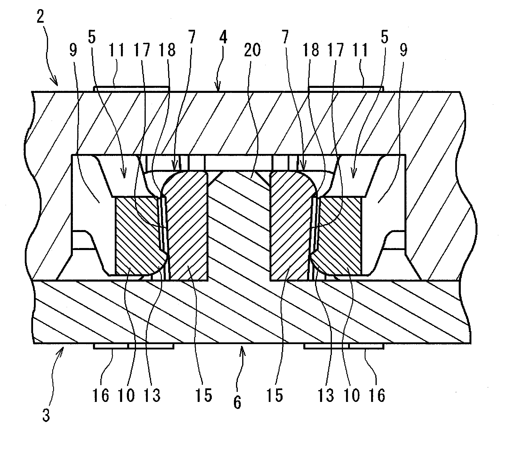
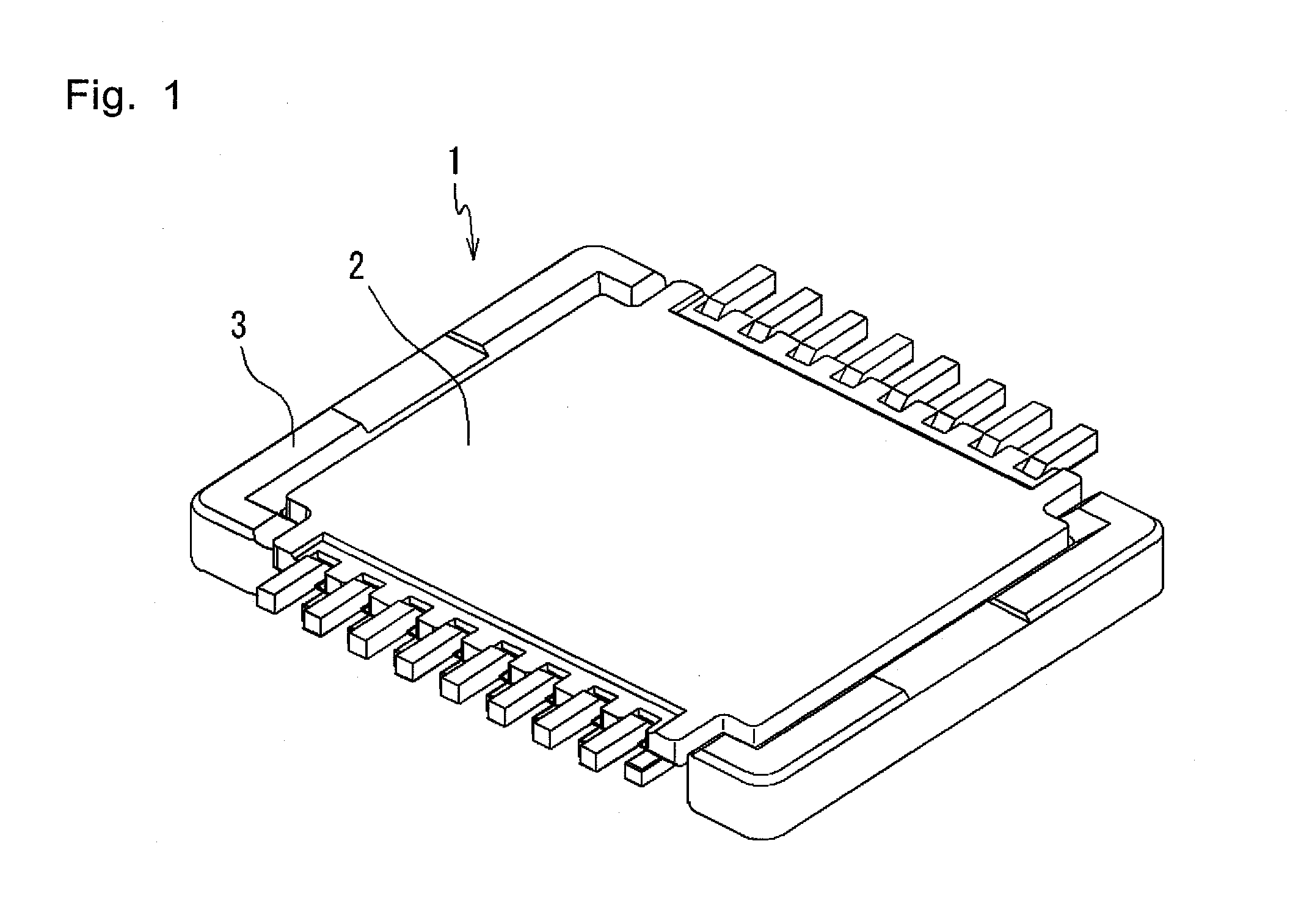
[0064]FIG. 1 shows a connector 1 of one embodiment of the present invention. The connector 1 consists of a socket (first connection member) 2 and a plug (second connection member) 3.

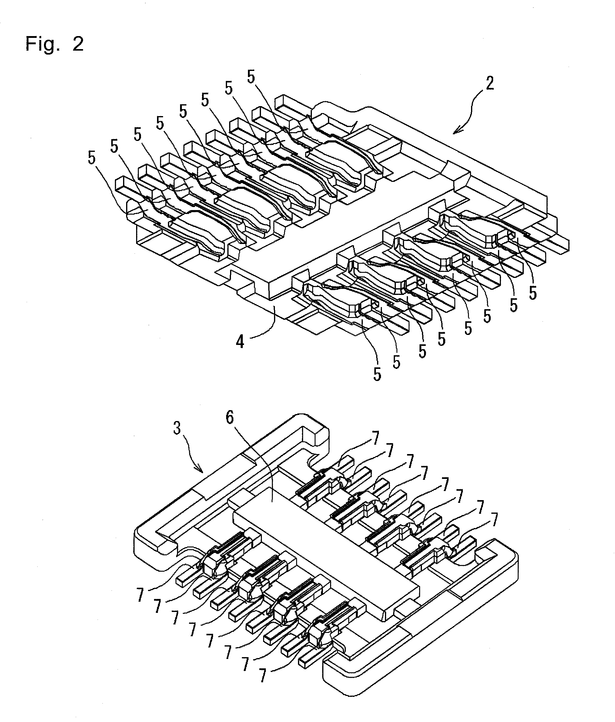
[0065]As shown in FIG. 2 and FIG. 3, the socket 2 retains a plurality of pairs of right and left female-type metal contacts 5 arranged in a plastic housing 4. Also, as shown in FIG. 2 and FIG. 4, the plug 3 retains a plurality of pairs of right and left male-type metal contacts (conductive members) 7 arranged in a p...


PUM

PropertyMeasurementUnit
voltageaaaaaaaaaa
conductiveaaaaaaaaaa
sizeaaaaaaaaaa

Abstract

A contact formed by electroforming and extended in a direction roughly perpendicular to a voltage application direction in the electroforming has a contact portion disposed at one end of the contact, which is brought into sliding contact with a conductive member along the voltage application direction in the electroforming.

Description

TECHNICAL FIELD[0001]The present invention relates to contacts and a connector.BACKGROUND ART[0002]For example, in a multi-pole connector mounted to a printed wiring board and connecting printed wiring boards so that they are superimposed, it is desired that the connector is shortened (a height reduction) in a fitting direction due to a reduction in size of equipment for housing a circuit.[0003]In order to reduce the height of the connector, it is necessary to shorten each contact (conductive terminal) in a fitting direction. The contacts require an elastic force for being press-fitted to each other in order to secure a conductive contact, and a fitting length to some extent so that the contacts are not easily separated.[0004]As described in Patent Documents 1 and 2, in a case where contacts are formed by bending a metal plate, a radius dimension for bending is required, so that there is a limitation in reducing the height in order to secure the fitting length. Further, in a case wh...

Claims


Application Information

Patent Timeline
Patent Type & Authority Applications(United States)
IPC IPC(8): C25D7/00H01R13/03H01R13/24
CPCH01R12/716H01R43/16H01R12/71H01R13/15H01R13/22H01R24/20
Inventor HEMMI, YOSHINOBUSEKI, KAZUMASANAGASAKA, SHOGOYAMASHITA, TOSHIO
Owner ORMON CORP
Why Eureka
Try Eureka