Flue gas analyser

a technology of flue gas and analyzer, which is applied in the direction of liquid/fluent solid measurement, furnace-tube steam boiler, lighting and heating apparatus, etc., can solve the problems of electrical oxygen sensor failure in the presence of a combination of nitrogen dioxide and a sufficiently high concentration

Inactive Publication Date: 2010-03-18
ALPHASENSE LTD
View PDF16 Cites 9 Cited by
  • Summary
  • Abstract
  • Description
  • Claims
  • Application Information

AI Technical Summary

Benefits of technology

[0007]According to a first aspect of the present invention there is provided a flue gas analyser for measuring the concentration of oxygen in flue gas, comprising an inlet for receiving gas for analysis, an electrochemical oxygen sensor, and water vapour removing means for reducing the relative humidity of received gas and / or nitrogen-containing-gas removing means for removing from received gas one or more gaseous species comprising nitrogen and oxygen which are either nitrogen dioxide, or formed from nitrogen dioxide in the presence of sufficient water vapour, which would otherwise lead to damage of the electrochemical oxygen sensor.
[0022]The nitrogen-containing-gas removing means and / or water vapour removing means may be located within the mass flow control member. The nitrogen-containing-gas removing means and / or water vapour removing means may be located intermediate the inlet and the mass flow control member. These arrangements can reduce damage to the mass flow control member in the presence of both nitrogen dioxide and a high concentration of water vapour, which is useful in embodiments where the mass flow control member is susceptible to damage in the presence of both nitrogen dioxide and a high concentration of water vapour. By “damage” we include blockage of the mass flow control member. The nitrogen-containing-gas removing means and / or water vapour removing means may be gas permeable and function as the mass flow control member.
[0029]Preferably, the flue conducts flue gas which, were it not for the presence of gas removing means and / or water vapour removing means, would reduce the operational lifetime of the flue gas analyser by at least a factor of ten.
[0033]Preferably, were it not for the presence of the nitrogen-containing-gas removing means and / or water vapour removing means, the flue gas would reduce the operational lifetime of the flue gas analyser by at least a factor of ten.
[0036]According to a fifth aspect of the present invention there is provided a method of developing a flue gas analyser which has an improved operational lifetime in the presence of nitrogen dioxide and water vapour with a relative humidity of at least 80% (preferably at least 90%, or at least 95%), comprising comparing the operational lifetime of a flue gas analyser including water vapour removing means for reducing the relative humidity of received gas and / or nitrogen-containing-gas removing means for removing from received gas one or more gaseous species comprising nitrogen and oxygen which are either nitrogen dioxide, or formed from nitrogen dioxide in the presence of sufficient water vapour, which would otherwise lead to damage of the electrochemical oxygen sensor and a flue gas analyser lacking said nitrogen-containing-gas and / or water vapour removing means in a gas sample comprising at least 5 ppm of nitrogen dioxide (preferably, at least 100 ppm of nitrogen dioxide) and having a relative humidity of at least 80% (preferably at least 90%, or at least 95%).
[0037]According to a sixth aspect of the present invention there is provided a method of developing a flue gas analyser which has an improved operational lifetime in the presence of nitrogen dioxide and a high concentration of water vapour comprising comparing the operational lifetime of a first flue gas analyser and a second flue gas analyser including at least one part which is made from a different material to a corresponding part in the first flue gas analyzer in the presence of gas samples comprising at least 5 ppm of nitrogen dioxide (preferably, at least 100 ppm of nitrogen dioxide) and having a relative humidity of at least 80% (preferably 90% and more preferably at least 95%).

Problems solved by technology

We have discovered that, surprisingly, electrochemical oxygen sensors fail in the presence of a combination of both nitrogen dioxide and a sufficiently high concentration of water vapour, typically at least 80% relative humidity.

Method used


Image

  • Flue gas analyser
  • Flue gas analyser
  • Flue gas analyser

Examples


Embodiment Construction

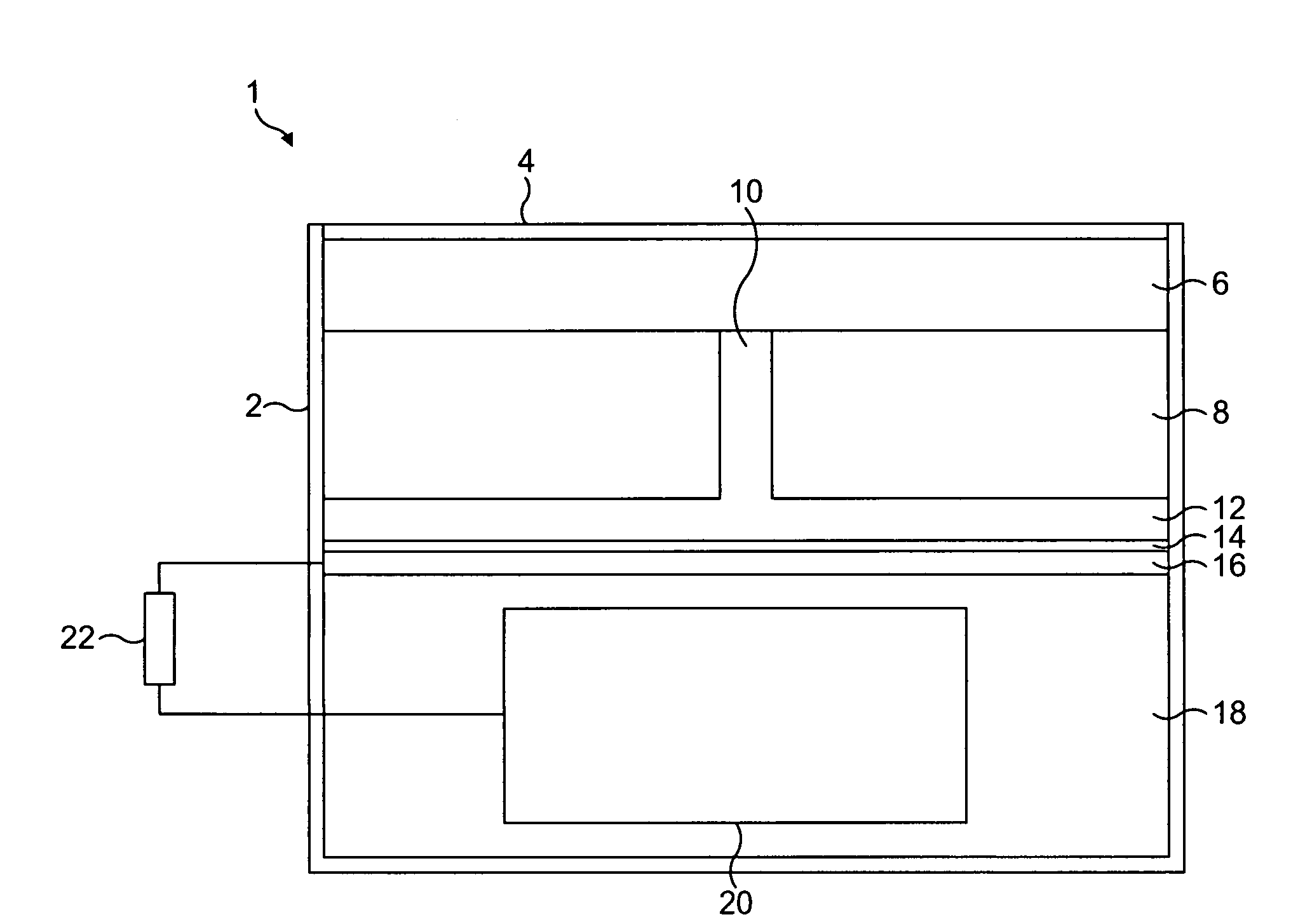
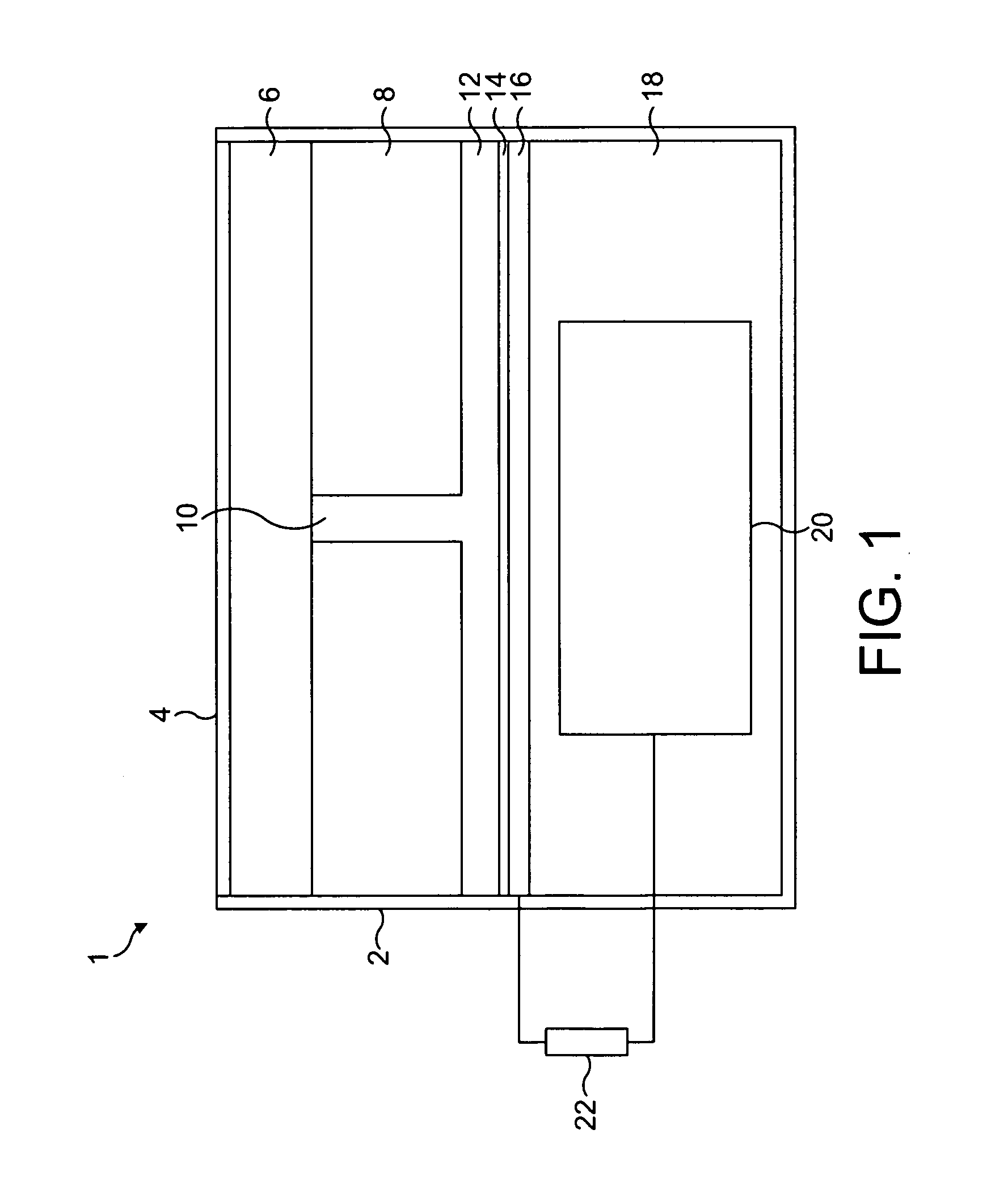
[0050]FIG. 1 illustrates oxygen sensing apparatus shown generally as 1, within a flue gas analyser. The flue gas analyser also includes carbon monoxide sensing apparatus for measuring the concentration of carbon monoxide and optionally other gas sensing apparatus for measuring additional gases. The oxygen sensing apparatus includes a housing 2 and an inlet 4 defined by holes through which a gas sample can penetrate the housing. Crystals of potassium permanganate 6 (functioning as nitrogen-containing-gas removing means) are located in a chamber intermediate the inlet and a mass flow control member 8 which takes the form of a block of ABS through the middle of which a narrow (10 extends. The opposite end of the capillary tube opens into a gas space 12 bounded by the mass flow control member and a hydrophobic PTFE membrane 14, which functions as liquid permeable electrolyte retaining means. The gas space typically has a depth of only a few microns to minimise its volume. The hydrophobi...


PUM

PropertyMeasurementUnit
diameteraaaaaaaaaa
diameteraaaaaaaaaa
humidityaaaaaaaaaa

Abstract

A flue gas analyser for measuring the concentration of oxygen in flue gas, comprising an electrochemical oxygen sensor and water vapour removing means for reducing the relative humidity of received gas and / or nitrogen-containing-gas removing means for removing from received gas one or more gaseous species comprising nitrogen and oxygen which are either nitrogen dioxide, or formed from nitrogen dioxide in the presence of sufficient water vapour, which would otherwise lead to damage of the electrochemical oxygen sensor,

Description

FIELD OF THE INVENTION[0001]The present invention relates to the field of flue gas analysers for measuring the concentration of oxygen in flue gas.BACKGROUND TO THE INVENTION[0002]Electrochemical oxygen sensors are in common use at the present time for measuring the concentration of oxygen in gas samples. Electrochemical oxygen sensors are used in flue gas analysers for measuring the concentration of oxygen in flue gas. Flue gas is the combustion product which exits through the flues of industrial or domestic boilers for heating water or generating power which burn fossil fuels, such as oil, gas and coal, or other plant derived fuels, such as wood or other biofuels.[0003]It has been known for some time that electrochemical gas sensors sometimes fail when measuring the concentration of oxygen in flue gas emitted by some boiler installations. This failure usually occurs within a few days to months of installation. Sometimes the failure is irreversible; sometimes the failure is reversi...

Claims


Application Information

Patent Timeline
Patent Type & Authority Applications(United States)
IPC IPC(8): G01N27/26F22B7/16
CPCG01N33/0014G01N27/404
Inventor SAFFELL, JOHN ROBERTDAWSON, DARRYL HIRST
Owner ALPHASENSE LTD
Why Eureka
Try Eureka