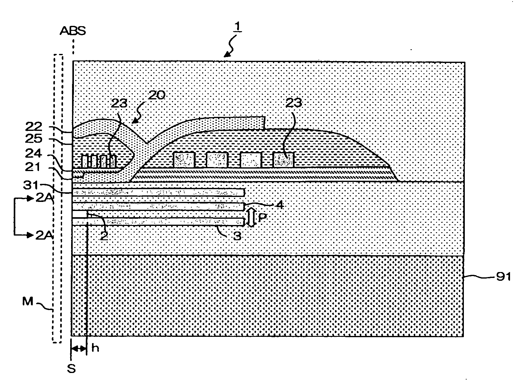
[0007]The present invention targets a thin film magnetic head having an MR laminated body where a first
magnetic layer (free layer) whose magnetization direction is changed according to an external
magnetic field, a nonmagnetic middle layer, and a second
magnetic layer (free layer) whose magnetization direction is changed according to the external
magnetic field are arranged in respective order to make contact with each other; and a bias magnetic field application means that is formed on an opposite surface from the
air bearing surface of the MR laminated layer and that applies a bias magnetic field orthogonal to the
air bearing surface to the MR laminated body. The objective of the present invention is to provide a thin film magnetic head where a
high rate of change in
magneto-resistance can be obtained by controlling the magnetization directions of two magnetic layers in a magnetic field-
free state to antiparallel directions to each other without relying upon a
magnetic interaction between these magnetic layers, and where the rate of change in magnetization resistance varies less, and where reduction of the read gap is easy.
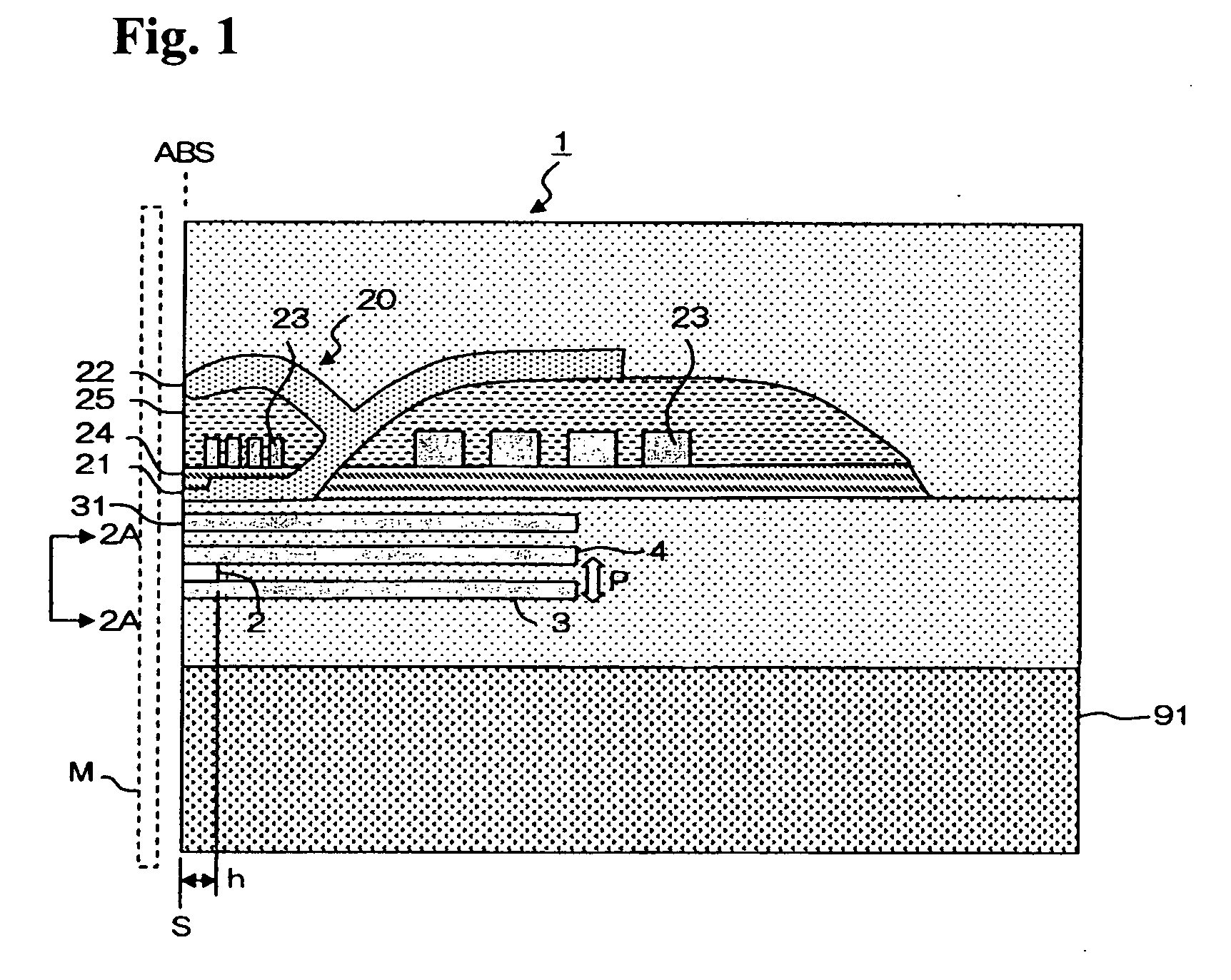
[0009]In the thin film magnetic head having such a configuration, an exchange-
coupling magnetic field from the first and second exchange-
coupling magnetic field application layers whose directions of magnetization are solidly fixed due to the exchange-coupling with the first and second antiferromagnetic layers, is transmitted to the first and second magnetic layers. The exchange-coupling magnetic field from the first exchange-coupling magnetic field
application layer and the exchange-coupling magnetic field from the second exchange-coupling magnetic field
application layer can be in antiparallel with each other, and the first and second magnetic layers are magnetized to the antiparallel direction from each other in the magnetic field-
free state. However, in actuality, since a bias magnetic filed in the orthogonal direction to the
air bearing surface is applied from the bias magnetic field application means, the first and second magnetic layers are magnetized to the
intermediate state between the antiparallel and parallel. This magnetization state is regarded as an initial magnetized state, and when the external magnetic field from the recording medium is applied, a relative angle formed with the magnetization directions of the first and second magnetic layers is changed according to the magnitude and orientation of the external magnetic field, and therefore, it becomes possible to detect the external magnetic field utilizing the
magneto-resistance effect.
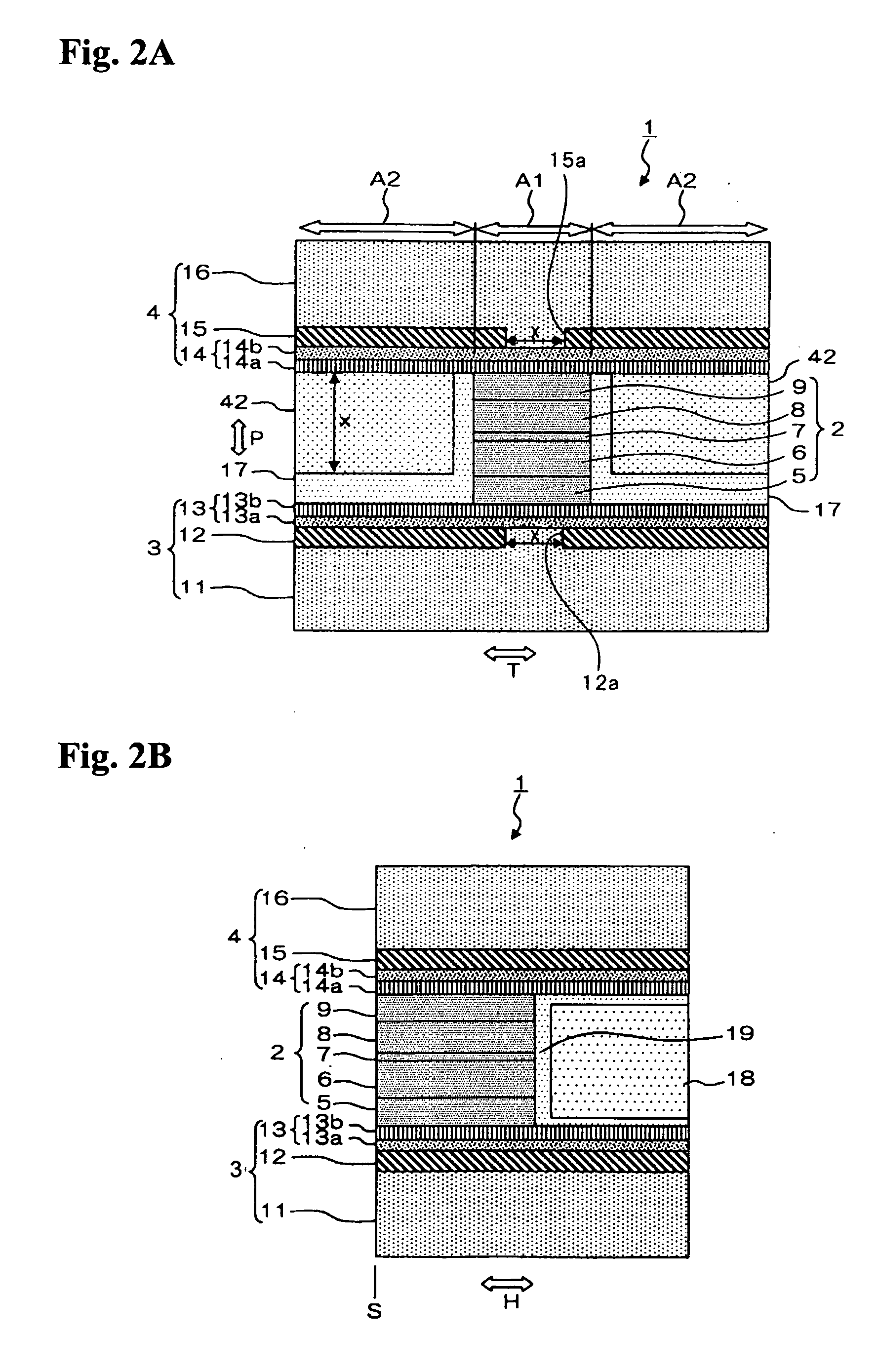
[0011]Further, in the present invention, because the first antiferromagnetic layer and / or the second antiferromagnetic layer contains a void part at least in a portion of the projection area toward the orthogonal direction to the film surface of the MR laminated body, or because the first antiferromagnetic layer and / or the second antiferromagnetic layer contains a thin portion at least in a portion of the projection area toward the orthogonal direction to the film surface of the MR laminated body, variation of a rate of change in magneto-resistance can be reduced. This point will be described hereafter.
[0013]Then, at least in a portion of the projection area to the orthogonal direction to the film surface of the MR laminated body whose
magnetic effect on the first and second magnetic layers is great, if it is designed such that a part of the antiferromagnetic layer is removed to form a void part in the antiferromagnetic layer, the variation and fluctuation in the magnetization direction of the exchange-coupling magnetic filed
application layer which is exchange-coupled with the antiferromagnetic layer due to the variation in the direction of the crystalline
magnetic anisotropy in the antiferromagnetic layer, can be reduced, and the variation and fluctuation in the magnetization directions of the first and second
magnetic layer can be reduced.
[0016]As described above, a thin film magnetic head where a
high rate of change in magneto-resistance can be obtained and where variation in the rate of change in magneto-resistance is small and where reduction of the read gap is easy, can be provided.

