Substrate processing apparatus and substrate conveying apparatus for use in the same

a technology for conveying apparatus and substrates, which is applied in the direction of de-stacking articles, furnaces, charge manipulation, etc., can solve the problems of increasing the footprint of the apparatus, not-yet-processed substrates cannot be sent thereto, and the processing speed of processed substrates cannot be improved, so as to achieve the effect of improving the processing speed and speed

Active Publication Date: 2010-03-18
DAINIPPON SCREEN MTG CO LTD
View PDF15 Cites 20 Cited by
  • Summary
  • Abstract
  • Description
  • Claims
  • Application Information

AI Technical Summary

Benefits of technology

[0014]An object of the present invention is to provide a substrate processing apparatus capable of improving a substrate processing speed while controlling the footprint of the apparatus.
[0015]Another object of the present invention is to provide a substrate conveying apparatus capable of shortening a time required for switching between batch conveyance in which a plurality of substrates are conveyed in a batch manner and one-by-one conveyance in which a substrate is conveyed one at a time and yet capable of simplifying the structure of the apparatus. Still another object of the present invention is to provide a substrate processing apparatus provided with such a substrate conveying apparatus.

Problems solved by technology

Therefore, when not-yet-processed substrates are sent to the main transfer mechanism, already-processed substrates cannot be expelled from the main transfer mechanism to the pusher, and, when already-processed substrates are expelled therefrom, not-yet-processed substrates cannot be sent thereto.
However, a structure formed according to this possible solution inevitably cause an increase in the footprint of the apparatus.

Method used


Image

  • Substrate processing apparatus and substrate conveying apparatus for use in the same
  • Substrate processing apparatus and substrate conveying apparatus for use in the same
  • Substrate processing apparatus and substrate conveying apparatus for use in the same

Examples


Embodiment Construction

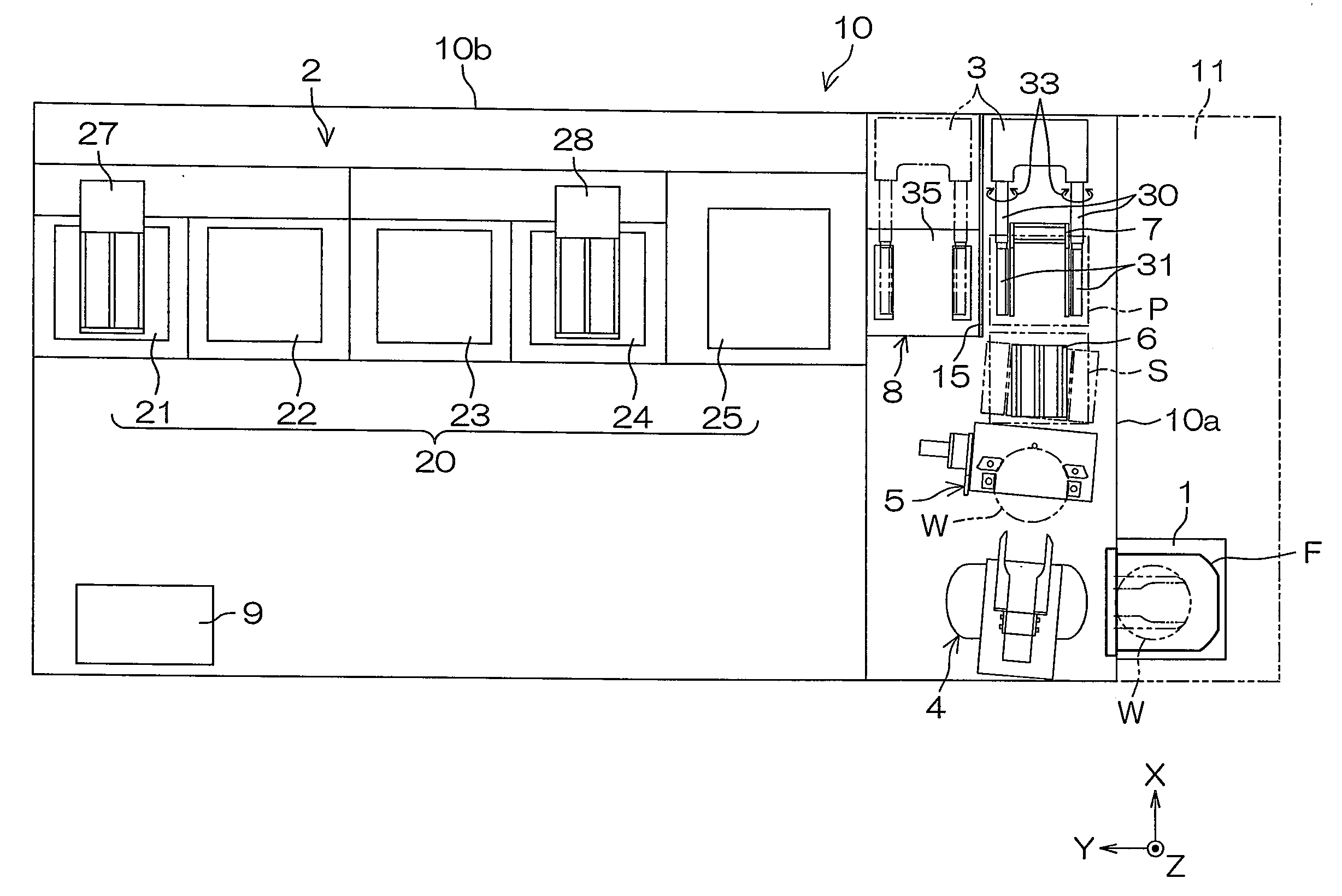
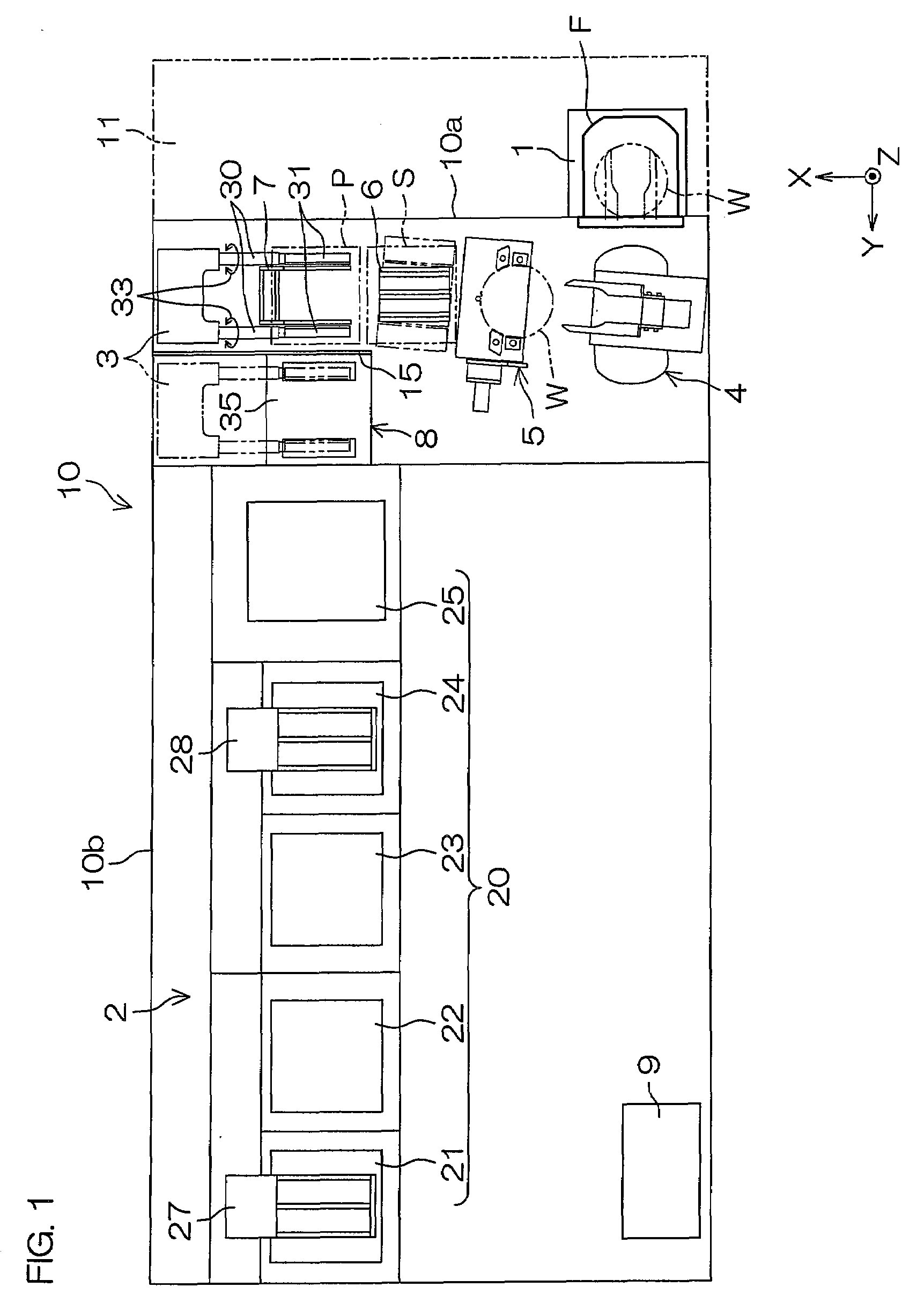
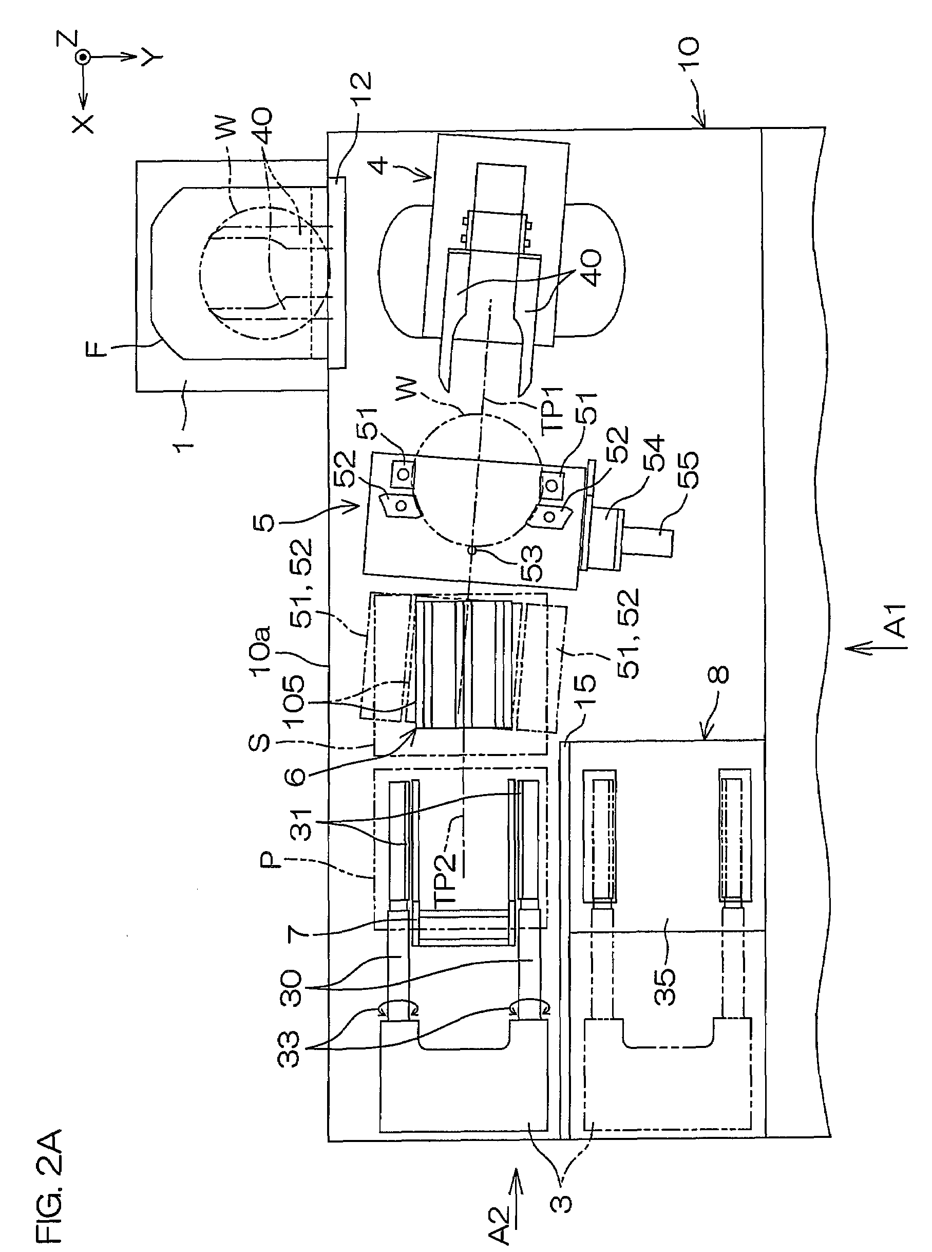
[0075]FIG. 1 is a schematic plan view for explaining the entire structure of a substrate processing apparatus according to an embodiment of the present invention. The substrate processing apparatus 10 includes a FOUP (front opening unified pod) holding portion 1, a substrate processing section 2, a main transfer mechanism 3, a carry-in-and-out mechanism 4, a posture changing mechanism 5, a pusher 6, a delivery mechanism 7, a chuck washing unit 8, and a controller (control unit) 9.

[0076]The FOUP holding portion 1 is disposed at a corner of the substrate processing apparatus 10 having a substantially rectangular shape when viewed planarly. The FOUP holding portion 1 is a pod holding portion that holds a FOUP F serving as a pod containing a plurality of substrates W (for example, twenty-five substrates) piled in a Z direction (i.e., up-down direction, or vertical direction) each of which assumes a horizontal posture. An automatic FOUP conveying apparatus 11 shown by a phantom line is d...


PUM


Abstract

A substrate processing apparatus includes a substrate processing section that processes a plurality of substrates assuming a vertical posture in a batch manner; a first traversing mechanism that laterally moves a first traverse holding portion along a first traversing path between a substrate transfer position and a substrate delivery position; a second traversing mechanism that laterally moves a second traverse holding portion along a second traversing path disposed below the first traversing path between the substrate transfer position and the substrate delivery position; an elevation mechanism that raises and lowers an elevation holding portion in the substrate transfer position; and a main transfer mechanism that conveys a plurality of substrates assuming a vertical posture in a batch manner between the substrate delivery position and the substrate processing section, the first and second traverse holding portions, and the elevation holding portion each holds a plurality of substrates assuming a vertical posture in a batch manner.

Description

BACKGROUND OF THE INVENTION[0001]1. Field of the Invention[0002]This invention relates to a substrate processing apparatus that applies processing onto a plurality of substrates in a batch manner and a substrate conveying apparatus installed in such a substrate processing apparatus. Examples of substrates to be processed or to be conveyed include semiconductor wafers, substrates for liquid crystal displays, substrates for plasma displays, substrates for FEDs (Field Emission Displays), substrates for optical disks, substrates for magnetic disks, substrates for magnet-optical disks, and substrates for photomasks.[0003]2. Description of Related Art[0004]A batch type substrate processing apparatus that applies processing onto a plurality of substrates in a batch manner has been used as a substrate processing apparatus that applies processing using a chemical solution onto substrates such as semiconductor wafers. An example of such a batch type apparatus is disclosed in Japanese Unexamin...

Claims


Application Information

Patent Timeline
Patent Type & Authority Applications(United States)
IPC IPC(8): H01L21/67B65G37/00B65G49/00B65G47/00H01L21/683H01L21/68H01L21/677
CPCH01L21/68707B65G25/04H01L21/67766H01L21/67313B65G49/061Y10S414/138H01L21/67781B65G49/067B65G59/02
Inventor MITSUYOSHI, ICHIROMURAMOTO, RYO
Owner DAINIPPON SCREEN MTG CO LTD
Why Eureka
Try Eureka