Medical guide element with diameter transition

a technology of transitional diameter and guide element, which is applied in the field of new introduction of guide element, can solve the problems of more lengthy and difficult hemostasis, and achieve the effect of reducing the flow of blood and sufficient length and diameter

Active Publication Date: 2010-03-18
GRAYZEL JEFFREY +1
View PDF48 Cites 19 Cited by
  • Summary
  • Abstract
  • Description
  • Claims
  • Application Information

AI Technical Summary

Benefits of technology

[0080]The inventions also include methods for creating and dilating an opening in the wall of a blood vessel or other anatomical structure. The method is a modification of the SDH technique that includes serial steps starting with inserting a needle, or other sharp tubular device, into the wall of the blood vessel to create the opening. The next step is inserting an elongate guide element of the present invention into the internal bore of the needle or tubular device. The distal segment of the guide element is of sufficient length and diameter to substantially reduce the flow of blood through the internal bore of the needle. A part of the distal segment extends beyond the distal tip of the needle, and therefore extends through the opening in the wall of the blood vessel and into the lumen of the vessel. Preferably the circumferential step is located proximal to the needle hub so that it can be seen and felt by the operator. However, it may optionally reside within the needle bore at any point outside the blood vessel, preferably at a point above skin level. The needle is then slidably removed from the blood vessel while keeping the distal segment of the elongate guide element in the lumen of the blood vessel and the circumferential step outside the blood vessel.
[0081]In the next step, a dilator is slid over the proximal segment of the guide element. The dilator has an interior passage of sufficient size to pass over the maximum outer diameter of the proximal segment of the guide element, but not large enough to pass over and beyond the circumferential step. The dilator has a tapered distal end with a distal tip whose outer diameter preferably is not greater than the outer diameter of the distal segment of the guide element at the step. The main body of the dilator has a maximum outer diameter greater than the outer diameter of the distal segment of the elongate element so that it can perform its function of dilating the target opening. The dilator is then advanced along the proximal segment until its distal tip abuts the guide element's circumferential step. Then the elongate guide element and the dilator are advanced together through the opening while maintaining the dilator tip in firm contact with the circumferential step to shield it from intervening tissue and the edges of the opening. The dilator is then advanced farther into the opening to dilate it.
[0082]The opening to be dilated need not be created by a needle to benefit from the smooth transition between guide element and dilator provided by the invention. Naturally-occurring openings or portions of an existing passage may be dilated more smoothly with the apparatus of the invention. Alternatively, openings can be created, for example, by cannulas and other tubular instruments, simple incisions, traumatic injury, and the like. Guide elements of the present inventions may include guidewires and other types of filaments

Problems solved by technology

In prior art devices, the discrete step-like increase in diameter from the filament or guidewire to the dilator tip is the principal factor which creates the resistance to entry of the dilator tip into the tissue, and the major cause of trauma and tearing of the arterial wall during procedures involving access to arteries, and as such also results in more lengthy and difficult hemostasis at the conclusion of the procedure when all implements are removed from the patient.

Method used


Image

  • Medical guide element with diameter transition
  • Medical guide element with diameter transition
  • Medical guide element with diameter transition

Examples


Embodiment Construction

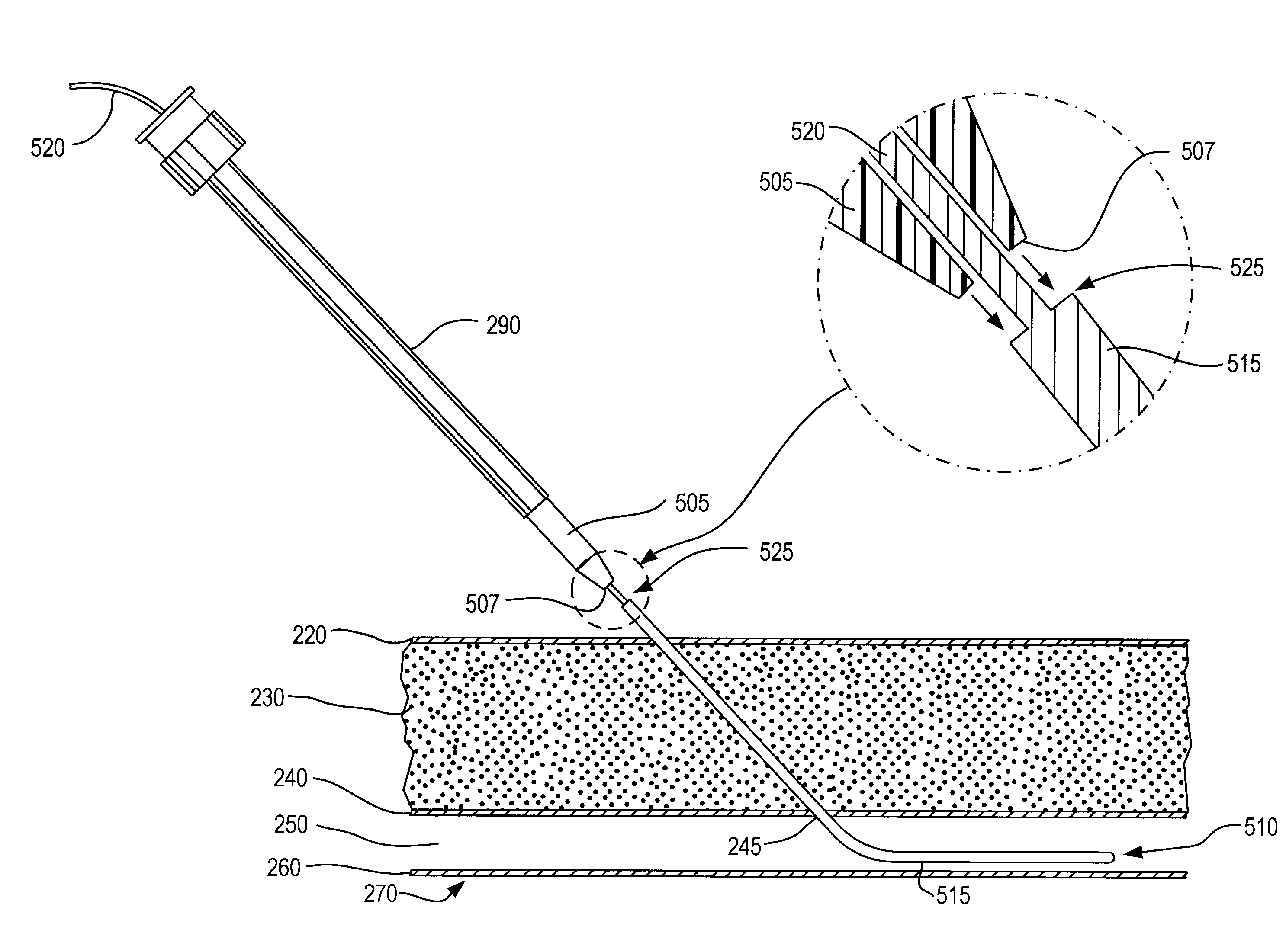
[0083]A first embodiment of a filament according to the present invention is shown in FIG. 4A. Filament 400 includes a proximal segment 405 and a distal segment 415 which at their juncture form an abrupt, circumferential step 410. Segments 405 and 415 may have the same or different configurations, but cylindrical configurations are preferred for both segments. Distal segment 415 serves multiple purposes: At its proximal end, it forms the abrupt step 410 which shields the distal tip of a dilator; its one or more regions of maximum diameter also block the backflow of blood through the needle, and also block the backflow of blood through the vessel puncture.

[0084]Proximal segment 405 has a maximum outer diameter 425 that is preferably substantially constant along the length of proximal segment 405. Distal segment 415 includes tip 420 and a cylindrical elongate portion 440 having a maximum outer diameter 430 that is preferably substantially constant along the length of cylindrical elong...


PUM


Abstract

Improved medical filaments for use with dilators to be inserted into a patient, for example into the vascular lumen, are provided, as well as combinations of filaments and dilators. Methods for use of such filaments and filament-dilator combinations are also described. The filament includes a proximal segment and a distal segment. The diameter of the distal segment is greater than the diameter of the proximal segment. The change in diameter is abrupt, providing a discrete step transition at a point along the filament which presents a proximally-facing surface on the distal segment. When the proximal segment of the filament is fully inserted into a dilator having a distal tip adapted for insertion into a patient, the dilator distal tip firmly abuts the proximally-facing end surface of the distal segment. The relative dimensions of the dilator tip and the discrete stepped transition of the filament provides full shielding or over shielding of the dilator tip, thereby facilitating passage of the dilator tip along the tissue track, through the puncture hole and into the orifice.

Description

FIELD OF THE INVENTION[0001]The invention generally relates to apparatus and methods for inserting catheters into the human body employing percutaneous techniques for vascular access. More particularly, the invention relates to a novel introducing guide element and to novel combinations of said introducing guide element with a matching dilating catheter.BACKGROUND[0002]In present medical practice, insertion of catheters into blood vessels and other body structures is most often accomplished by the percutaneous technique. The Percutaneous Technique is a term of art for a transcutaneous method that avoids surgical cut-down and dissection. Instead, a hollow-bore needle is employed to penetrate the skin or surface, traverse the subcutaneous tissue and other intervening structures, and enter the lumen of the blood vessel or body structure. Then a tracer or flexible filament, typically in the form of a metallic guidewire, is inserted through the bore of the needle so that it enters the va...

Claims


Application Information

Patent Timeline
Patent Type & Authority Applications(United States)
IPC IPC(8): A61M25/09A61M29/02
CPCA61M25/09A61M29/00A61M2025/09175A61M2025/09125A61M2025/09083A61M25/0606A61M29/02A61M2210/1021A61M2210/1078A61M2210/122A61M2210/125A61M25/0618A61M25/0643A61M25/0662A61M25/09041A61M2205/0216A61M2210/1082
Inventor GRAYZEL, JEFFREYGRAYZEL, JOSEPH
Owner GRAYZEL JEFFREY
Why Eureka
Try Eureka