Unlock instant, AI-driven research and patent intelligence for your innovation.

Atomic force microscope and interaction force measurement method using atomic force microscope

a technology of interaction force and microscope, which is applied in the field ofatomic force microscope, can solve the problems of inability to directly and experimentally obtain the interaction force, the electrostatic force fsub>ele /sub>completely zero, and the conventional method for computing the short-range interaction force fsub>sr /sub>, so as to reduce the amount of change, short-range interaction force, and the effect of reducing the creep of the piezoelectric elemen

Inactive Publication Date: 2010-03-18
OSAKA UNIV +1
View PDF6 Cites 3 Cited by
  • Summary
  • Abstract
  • Description
  • Claims
  • Application Information

AI Technical Summary

Benefits of technology

[0062]With the atomic force microscope and the interaction force measurement method using an atomic force microscope according to the present invention, the influence of the electrostatic force which is a factor of a long-range interaction force disappears in the computational process. Therefore, it is not necessary to apply a bias voltage for neglecting the electrostatic force's influence, i.e. for compensating the contact potential difference between the probe and the sample surface. Hence, even for the sample such as an insulator sample to which a bias voltage is difficult to apply, a short-range interaction force can be obtained without being affected by the electrostatic force.
[0063]Conventionally, it has been necessary to obtain a Δf curve with the range scale between a few and several tens of nm above each of the target atom and atomic defect. However, the present invention only requires the measurement of a Δf curve with the range scale from 0.5 nm to at most approximately 1 nm. This reduces the amount of change in the voltage applied to the piezoelectric element for oscillating the probe, which decreases the piezoelectric element's creep and increases the accuracy of the distance control. This also prevents the probe from getting accidentally damaged by coming into contacting with the sample surface. In addition, since the time required for the measurement of a Δf curve can also be shortened, the distance between the probe and the sample surface is less influenced by a thermal drift during the measurement.
[0064]Conventionally a computational process of the conversion from a Δf curve into an F curve has been required twice. By contrast, the present invention requires this computational process only once. Since the time required for this computational process is relatively long, the time period for obtaining the result will be shortened because the number of computational processes is halved. This time-reduction effect and the aforementioned time-reduction effect for the Δf curve's measurement itself bring about the improvement in the throughput.
[0065]Moreover, the enhancement of the measurement throughput and the ease of analysis additionally make it easy to perform a two-dimensional mapping measurement of the short-range interaction force above a sample surface and a two-dimensional mapping measurement of the potential obtained from a short-range interaction force.

Problems solved by technology

Although it is possible to obtain much information from the interaction force between the probe and the sample surface as will be described later, an FM-AFM has a disadvantage in that the interaction force cannot be directly and experimentally obtained.
However, the aforementioned conventional method for computing the short-range interaction force FSR has some problems as follows.
However, applying this bias voltage does not always make the electrostatic force Fele completely zero, whose effect may not be negligible and decrease the accuracy.
In addition, in the case of an insulator sample such as an ionic crystal, the compensation of the contact potential difference is virtually impossible since it is difficult to apply a bias voltage between the probe's tip and the sample surface.
This might cause the piezoelectric element's creep (i.e. a phenomenon in which a gradual displacement occurs even while the applied voltage is kept constant), which causes concern about the accuracy decrease of the position control.
In addition, since the acquisition of a Δf curve with a long range scale requires a long measurement time, the effect of the drift of the probe-sample surface distance due to the thermal expansion of the probe or sample becomes prominent.
In particular, although obtaining the short-range interaction force of only one point poses no problem, obtaining the short-range interaction force of a plurality of points takes an impractically long period of time.

Method used


Image

  • Atomic force microscope and interaction force measurement method using atomic force microscope
  • Atomic force microscope and interaction force measurement method using atomic force microscope
  • Atomic force microscope and interaction force measurement method using atomic force microscope

Examples


embodiments

[0110]One example of the concrete measurement result by the measurement method in accordance with the aforementioned procedure will be explained, being compared to a conventional measurement method.

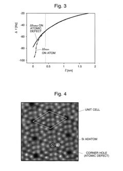
[0111]As the sample surface which is to be measured, a Si(111)7×7 reconstructed surface was used. FIG. 4 is an FM-AFM concave-convex observation image of the sample surface in an ultra-high vacuum. The scan range was 8 nm×8 nm. On the sample surface (first layer), a rhombic unit cell composed of twelve Si adatoms (or adsorbed atoms) exists, and an atomic defect which is called a corner hole is observed at each of the four corners of the unit cell.

[0112]For the sample surface, the contact potential difference between the probe and the sample surface was measured and it was as small as 22.5 mV. Therefore, the bias voltage to be applied between the probe and the sample surface was set to be zero. (Although the application of a bias voltage is not necessary in the measurement method according...


PUM


Abstract

A frequency shift Δf obtained by an FM-AFM can be expressed by a simple linear coupling of a ΔfLR derived from a long-range interaction force and a ΔfSR derived from a short-range interaction force. Given this factor, a Δf curve on an atomic defect and a Δf curve on a target atom on the sample surface are each measured for only a relatively short range scale (S1 and S2), and a difference Δf curve of those two curves is obtained (S3). Since the difference Δf curve is derived only from a short-range interaction force, a known conversion operation is applied to this curve obtain an F curve which illustrates the relationship between the force and the distance Z, and then the short-range interaction force on the target atom is obtained from the F curve (S4). Since the range scale in measuring the Δf curve can be narrowed, the measurement time can be shortened, and since the conversion from the Δf curve into F curve is required only once, the computational time can also be shortened. Consequently, in obtaining the short-range interaction force which acts between the atom on the sample surface and the probe, the time required for the Δf curve's measurement and the computational time are shortened, which leads to accuracy improvement and throughput enhancement.

Description

TECHNICAL FIELD[0001]The present invention relates to an atomic force microscope (AFM). In particular, it relates to a frequency modulation atomic force microscope (Frequency Modulation-AFM or FM-AFM), and an interaction force measurement method for measuring a short-range interaction force which acts between a probe and a sample surface when the probe is adjacent to the sample surface by using an atomic force microscope.BACKGROUND ART[0002]An atomic force microscope (AFM) is an apparatus for measuring the force which interacts between a probe with a sharp tip and a sample surface from the displacement of a cantilever, and one-dimensionally or two-dimensionally scanning the sample surface with the probe to obtain the sample surface's information, e.g. its geometry. One known type of AFM is an FM-AFM with a frequency modulation detection system. In an FM-AFM, a cantilever holding a probe approximate to the distance from the sample surface at the atomic level is oscillated with the me...

Claims


Application Information

Patent Timeline
Patent Type & Authority Applications(United States)
IPC IPC(8): G01Q60/24G01Q30/04G01Q60/32
CPCB82Y35/00Y10S977/863G01Q60/32G01Q30/04
Inventor OTA, MASAHIROOYABU, NORIAKIABE, MASAYUKICUSTANCE, OSCARSUGIMOTO, YOSHIAKIMORITA, SEIZO
Owner OSAKA UNIV