Front fascia plasma-induced drag reduction device

Inactive Publication Date: 2010-03-25
HONDA MOTOR CO LTD
View PDF8 Cites 26 Cited by
  • Summary
  • Abstract
  • Description
  • Claims
  • Application Information

AI Technical Summary

Benefits of technology

[0007]The present invention provides a vehicle front end that reduces the drag effect on the vehicle as compared to the vehicle front ends of the prior art. Particularly, the present invention provides a front fascia that manipulates air flowing underneath the vehicle so as to reduce air flow impingement on the ground, reduce localized high pressure regions of air flow underneath the vehicle, and thereby reduce the drag acting on the vehicle. The present invention reduces the drag by providing a plasma-induced drag reduction device on the vehicle front fascia.
[0008]The plasma-induced drag reduction device is mounted on an underside surface of the vehicle front fascia. The device applies a force on an air flowing past the underside of the front fascia in a direction toward the vehicle and away from the ground. The force applied to the air flow directs the air flow away from the ground, and therefore reduces the amount of air flow that impinges on the ground. The device is formed of a first and s

Problems solved by technology

However, due to limitations presented by other facets of automotive design, automobile exteriors can only be streamlined to a certain extent.
Thus, even the most streamlined, aerodynamic vehicles experience aerodynamic drag.
Further, while a streamlined shape works well with high-performance sports vehicles or ultra-fuel efficient competition vehicles, other types of vehicles are not amenable to such a design.
Vehicles having blunt front ends experienc

Method used


Image

  • Front fascia plasma-induced drag reduction device
  • Front fascia plasma-induced drag reduction device
  • Front fascia plasma-induced drag reduction device

Examples


Embodiment Construction

[0019]The invention will now be described in accordance with its preferred embodiments. The description with reference to the figures is intended to simplify the explanation of the invention and is not meant to limit the scope of the invention.

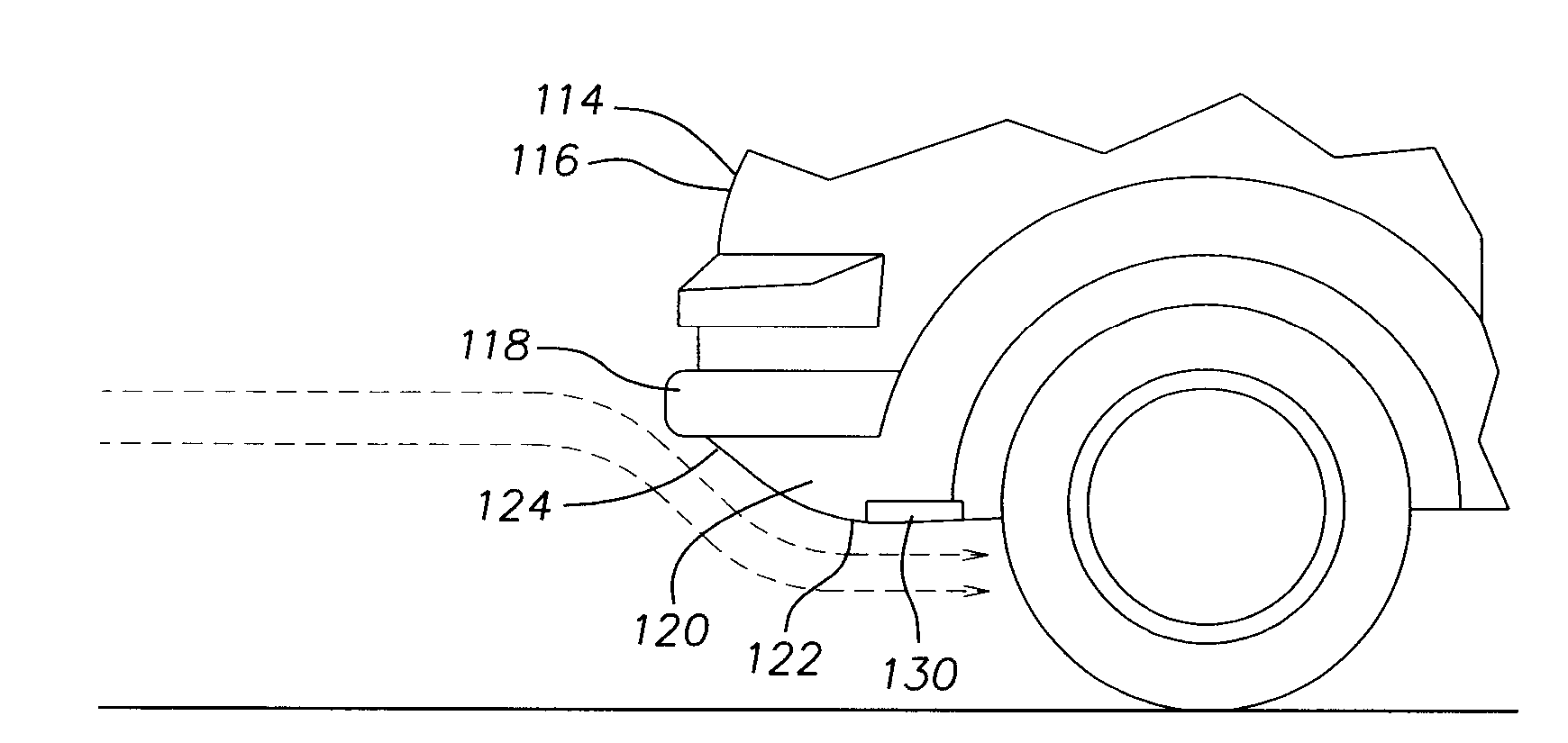
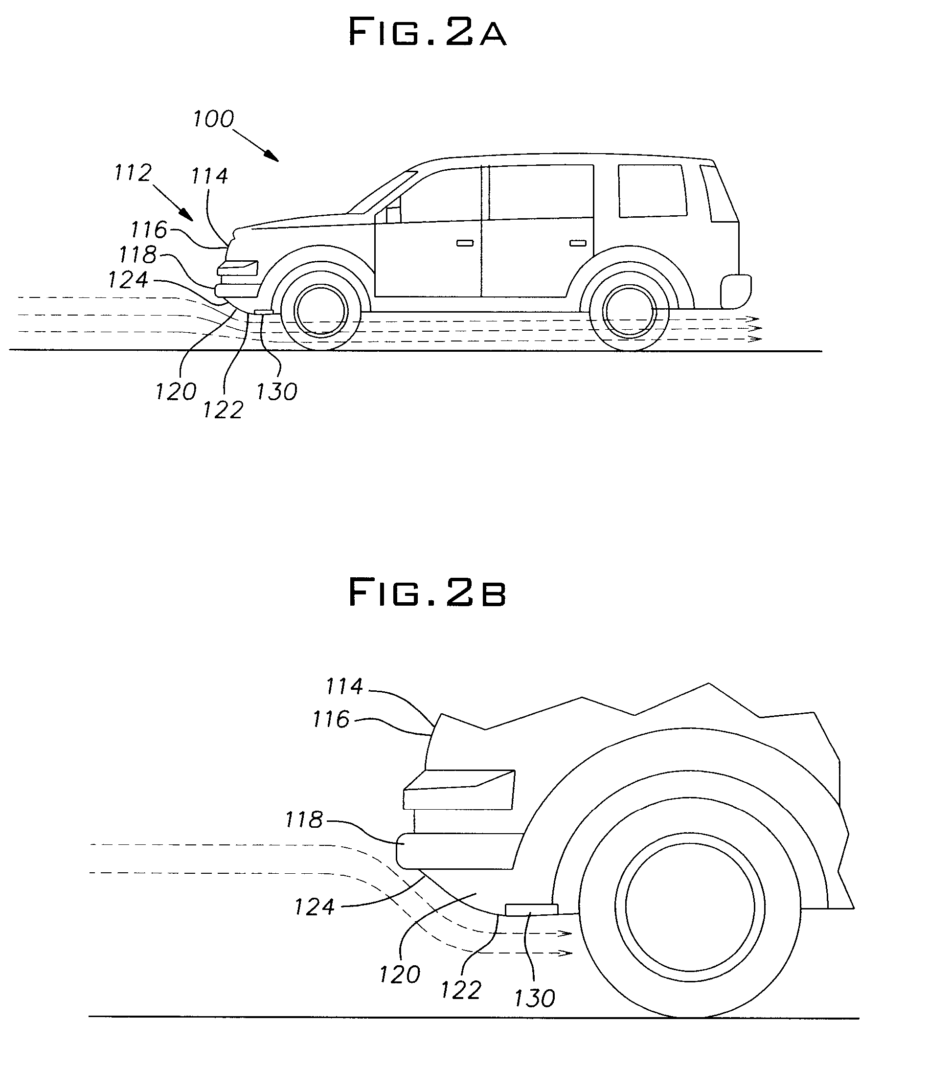
[0020]With reference to FIGS. 2A and 2B, a vehicle 100 having a front fascia 120 of the present invention is shown. The vehicle 100 of the exemplary embodiment is a Sports Utility Vehicle, however, the present invention is amenable to all variety of automobiles. The vehicle 100 has a front end 112 where headlights 114, a grille 116, a front bumper 118, and the front fascia 120 are disposed. The front fascia 120 is mounted below the front bumper 118, and includes an underside surface 122 and a frontal surface 124. The frontal surface 124 is generally perpendicular to the ground, and tapers into the underside surface 122, which is generally parallel to the ground.

[0021]To solve the problems associated with drag encountered by conventional vehicl...


PUM


Abstract

A plasma-induced drag reduction device is mounted on an underside of a vehicle front fascia. The drag reduction device has a dielectric substrate formed of a dielectric material, a first electrode mounted on a bottom, exposed surface of the dielectric substrate, and a second electrode mounted a top surface of the dielectric substrate and insulated by the dielectric substrate, and a power source connected to the first and second electrodes. The second electrode is disposed in a rearward direction relative to the first electrode. When activated, the device generates a plasma region that attracts an air flow passing underneath the vehicle, reducing the separation of the flow field and thereby reducing the impingement of the air flow on the ground and reducing the drag on the vehicle.

Description

BACKGROUND OF THE INVENTION[0001]In an attempt to optimize the energy used by vehicles, as well as improve vehicle performance, many factors relating to the air flowing around vehicles are considered. Particularly, to reduce the effect of aerodynamic drag, many vehicles are given streamlined, aerodynamic shapes. Such shapes allow the vehicle to slice through the air, thereby reducing the effect of drag on the vehicle. However, due to limitations presented by other facets of automotive design, automobile exteriors can only be streamlined to a certain extent. Thus, even the most streamlined, aerodynamic vehicles experience aerodynamic drag. Further, while a streamlined shape works well with high-performance sports vehicles or ultra-fuel efficient competition vehicles, other types of vehicles are not amenable to such a design. Particularly, certain sedans maintain a blunt front end for design reasons, while many trucks and SUVs maintain the blunt front ends out of both necessity and fo...

Claims


Application Information

Patent Timeline
IPC IPC(8): B62D35/00H01J7/24
CPCB62D35/00F15D1/12B62D35/02Y02T10/82Y02T10/88
Inventor RAMSAY, THOMAS
Owner HONDA MOTOR CO LTD
Why Eureka
Try Eureka