
Projection display apparatus

a technology of projection display and display screen, which is applied in the direction of projectors, instruments, optics, etc., can solve the problems of reducing image quality and speck (or speckle noise) to occur, and achieve the effect of reducing speckle nois

Inactive Publication Date: 2010-03-25
MITSUBISHI ELECTRIC CORP
View PDF6 Cites 17 Cited by
  • Summary
  • Abstract
  • Description
  • Claims
  • Application Information

AI Technical Summary

Benefits of technology

[0004]The present invention is directed to overcome the foregoing problems, and an object thereof is to provide a projection display apparatus capable of reducing speckle noise, without the image of a flaw or dust noticeable on the screen even if it exists in or on an optical component.
[0007]According to the invention, the speckle noise can be reduced with no image of a flaw or dust noticeable on a screen even if it exists in or on an optical path difference generating element.

Problems solved by technology

In such conventional display apparatuses, the above-described optical element provides an optical path difference to the optical beam, which leads to mutual interference between optical beams, thereby causing speckle (or speckle noise) to occur.
However, as shown in Japanese Unexamined Patent Publication No. 2002-90881, a problem is that when a flaw exists in or dust on the optical component for an apparatus having an optical component causing an optical path difference simply disposed in an optical path, the image of the flaw or dust is projected on the screen, thus resulting in an image defect on the screen, which leads to a reduction in image quality.

Method used


Image

  • Projection display apparatus
  • Projection display apparatus
  • Projection display apparatus

Examples


embodiment 1

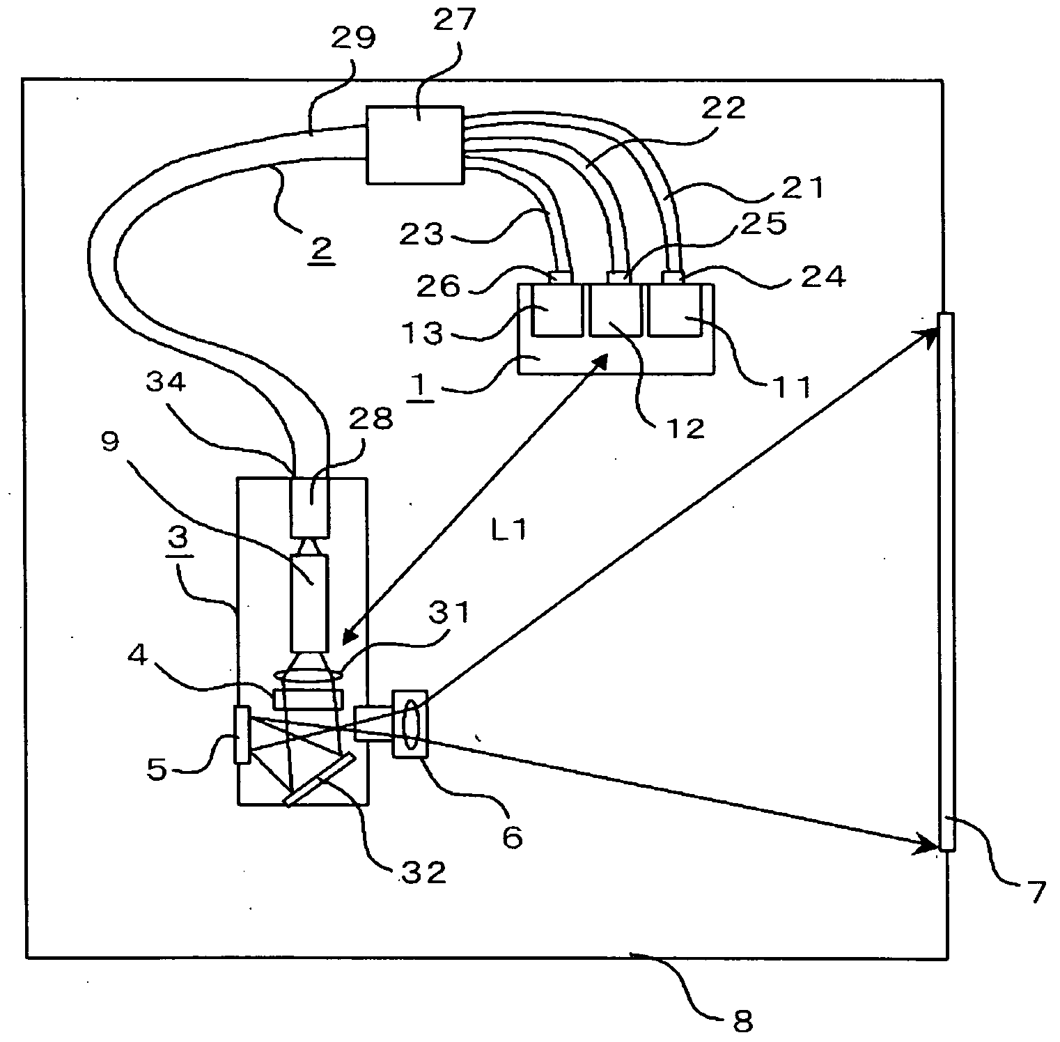
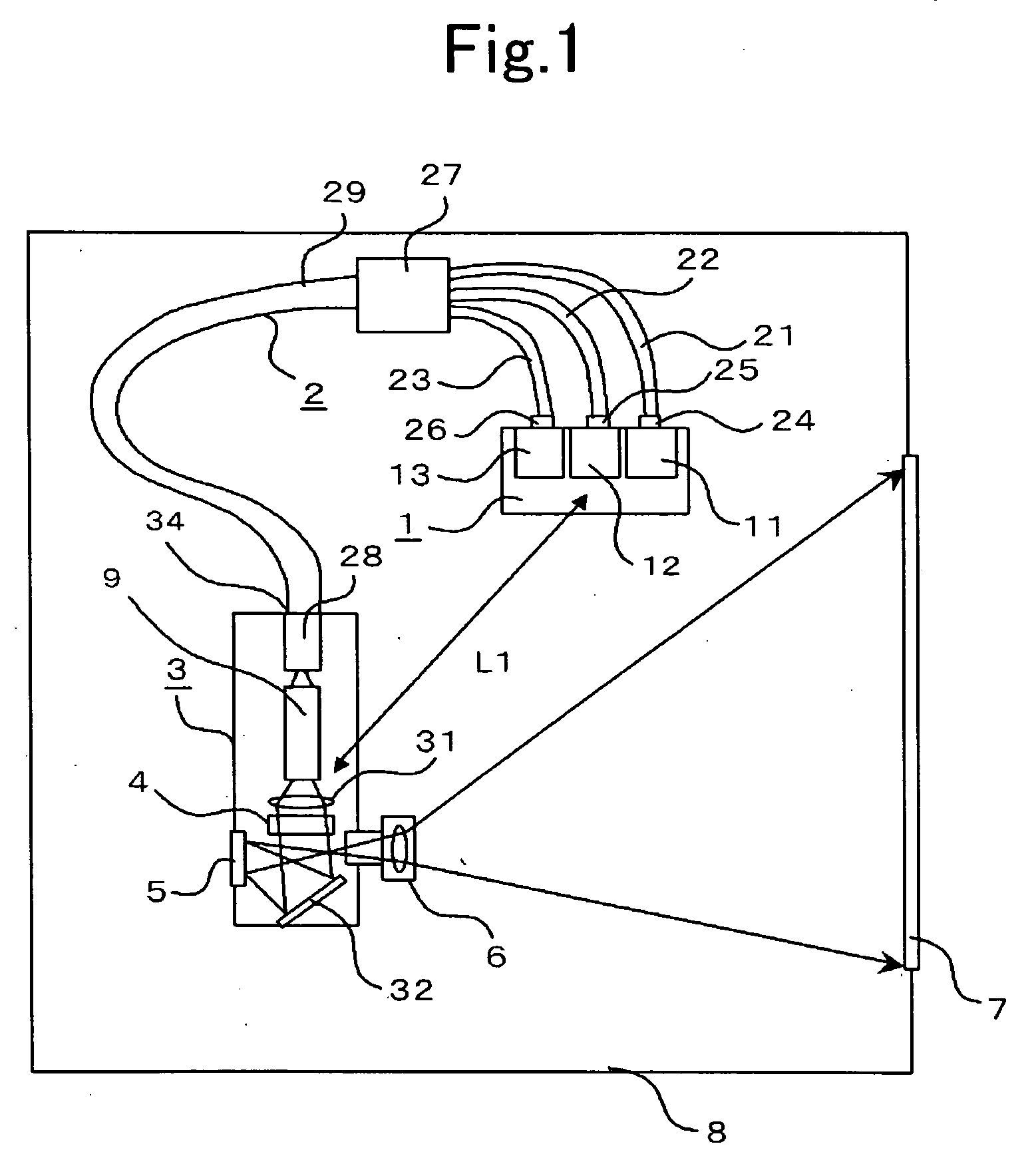
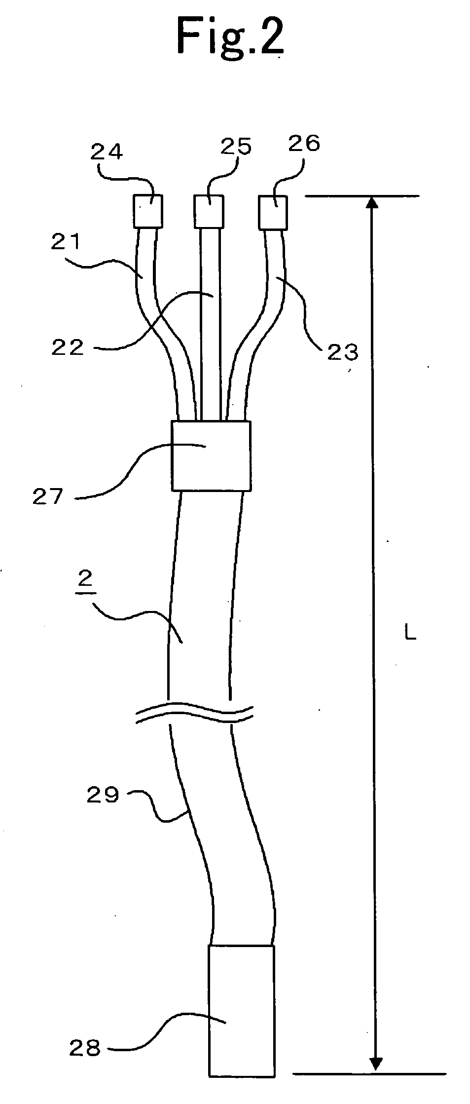
[0019]FIG. 1 is a view illustrating a configuration of a projection display apparatus according to Embodiment 1 of the present invention, while FIG. 2 is that of an optical fiber group 2 according to Embodiment 1 thereof. The projection display apparatus, as shown in FIG. 1, is configured with a laser beam source 1, an optical fiber group 2, an optical engine 3, a magnification projection lens 6, and a screen 7, and a casing 8 housing them.

[0020]The laser beam source 1 includes a laser source unit 11 for emitting a green laser beam, a laser source unit 12 for emitting a red laser beam, a laser source unit 13 for emitting a blue laser beam, and a drive control circuit (not shown) for driving the laser source units 11-13. The laser beam source emits, based upon image signals produced from an image signal generation circuit (not shown), the green, red, or blue laser beam for each several milli-seconds so that the emission times of the optical beam from the laser source units 11-13 do n...

embodiment 2

[0050]FIG. 7 is a cross-sectional view illustrating the placement of major components provided inside a projection display apparatus according to Embodiment 2, and FIG. 8 is a rear perspective view illustrating the projection display apparatus according thereto. In FIGS. 7 and 8, the same reference numerals refer to elements that are the same as or similar to those illustrated in FIG. 1, and description on like elements will not be provided herein. Here, FIG. 8 shows the rear portion of the casing with an exterior rear cover 81 removed therefrom.

[0051]The casing has an aperture for mounting the screen 7 at its front side, and a compartment space 80 for housing the laser beam source 1 and the optical fiber group 2 at its rear portion. The compartment space 80 is configured by a recessed portion 82 formed by depressing the rear of the casing 8, and the exterior rear cover 81 for covering the recessed portion 82. An enclosure box 14, which houses the laser beam source 1 thereinside, is...

embodiment 3

[0057]FIG. 10 is a rear perspective view of a projection display apparatus according to Embodiment 3. In FIG. 10, the same reference numerals refer to elements that are the same as or similar to those illustrated in FIG. 8, and description on like elements will not be provided herein. Referring to FIG. 10, by circularly bundling and then installing the optical fiber group 2, the length of the optical fiber group 2 can be extended, thereby achieving a more effect on speckle noise reduction. Moreover, a sufficient effect on speckle noise reduction can also be achieved for the installation of the fiber group 2 in a situation where the enclosure box 14 and the optical engine 3 are hard to place apart from each other, and also for its installation inside the projection display apparatus with a small screen size.


PUM


Abstract

A projection display apparatus is provided that is capable of reducing speckle noise, with no image of a flaw or dust noticeable in or on a screen even if it exists in or on an optical component. The projection display apparatus includes a glass rod that makes uniform an optical beam emitted from a laser beam source; a lens that focuses an optical beam passing through the glass rod; a diffusion layer that provides an optical path difference distribution to the optical beam focused using the focusing element, the diffusion layer being optically conjugated with an incident end of the glass rod by the focusing element; a display device that spatially modulates the optical beam provided with the optical path difference distribution by the diffusion layer; and a magnification projection lens that projects on a screen an optical beam modulated by the modulator.

Description

FIELD OF THE INVENTION[0001]The present invention relates to projection display apparatuses each having a function of speckle noise reduction, that produce high-quality images by reducing the speckle.BACKGROUND OF THE INVENTION[0002]Conventional projection display apparatuses represent images by conducting to a DMD (digital micro-mirror device)™ or an optical valve, an optical beam emitted from an optical source via optical elements such as lenses and mirrors and then projecting an output imaging beam on a screen. In such conventional display apparatuses, the above-described optical element provides an optical path difference to the optical beam, which leads to mutual interference between optical beams, thereby causing speckle (or speckle noise) to occur. Thus, in order to reduce occurrence of the speckle, an optical component causing a slight optical path difference is arranged to be placed in an optical path. Furthermore, in order to effectively reduce the occurrence of the speckl...

Claims


Application Information

Patent Timeline
Patent Type & Authority Applications(United States)
IPC IPC(8): G02B27/48G03B21/14G03B21/10
CPCG02B27/1033G03B21/14G02B27/48G03B21/208
Inventor YAGYU, SHINJI
Owner MITSUBISHI ELECTRIC CORP
Learn More