Lens for Solid-State Light-Emitting Device

a light-emitting device and solid-state technology, applied in the field of high-performance lenses, can solve the problems of not meeting the requirements of common problems, affecting the uniformity of illumination, and wasting available light energy, and achieves the effects of uniform illumination, low profile, and flexibility in design

Inactive Publication Date: 2010-03-25
LEWIN IAN +1
View PDF10 Cites 73 Cited by
  • Summary
  • Abstract
  • Description
  • Claims
  • Application Information

AI Technical Summary

Benefits of technology

[0035]It is another object of this invention to provide a system of optical control that creates low emission of light intensity toward ground areas that are close to the luminaire containing an array of LED's.
[0036]It is another object of this invention to provide a system of optical control that creates good illumination of areas that are within the area to be lighted by an LED luminaire but are distant from the LED based luminaire.
[0037]It is another object of this invention to provide a system of optical control that tunes and tailors the pattern of light incident on the ground in the vicinity of the LED based luminaire such that relatively uniform illuminance is created over the entire area desired to be illuminated by an LED luminaire.
[0038]It is another object of this invention to include allowing the placement of an array of LED's on a surface that can be simply formed.
[0039]It is another object of this invention to provide a system of optical control that has a flexibility in design allowing for a desired pattern of light to be generated by or for various shapes and sizes of luminaire housings.
[0040]It is another object of this invention to provide a compact luminaire that has a low profile and is otherwise of less bulk and mass than luminaires for use with HID lamps.

Problems solved by technology

The design of a lens for solid-state light-emitting devices, such as, but not limited to, LED's, presents several significant problems.
In contemporary HID street and area lighting systems the area directly below the HID lamp is usually lighted at too high a level, forming a pool of excess light, which is not useful and a wasteful allocation of available light energy.
Another problem presented to the lighting designer in the design of street lighting systems is to design a system to project an adequate level of light at points distant from the luminaire as the light intensity required to produce a given level of illuminance is very much greater, due to the inverse square law related to illuminance drop off, than for points close to or directly beneath the luminaire.
HID lamps produce a generally toroidal intensity distribution and thus the optical systems for distributing light from the high intensity lamps are not helpful as optical systems for distribution of light generated by LED based systems.
However such a light distribution arrangement does not meet the requirements commonly encountered in designing an outdoor lighting system.

Method used


Image

  • Lens for Solid-State Light-Emitting Device
  • Lens for Solid-State Light-Emitting Device
  • Lens for Solid-State Light-Emitting Device

Examples


Embodiment Construction

[0073]In the following description, and for the purposes of explanation, numerous specific details are set forth in order to provide a thorough understanding of the various aspects of the invention. It will be understood, however, by those skilled in the relevant arts, that the present invention may be practiced without these specific details. In other instances, known structures and devices are shown or discussed more generally in order to avoid obscuring the invention. In many cases, a description of the operation is sufficient to enable one to implement the various forms of the invention. It should be noted that there are many different and alternative configurations, devices and technologies to which the disclosed inventions may be applied. The full scope of the inventions is not limited to the examples that are described below.

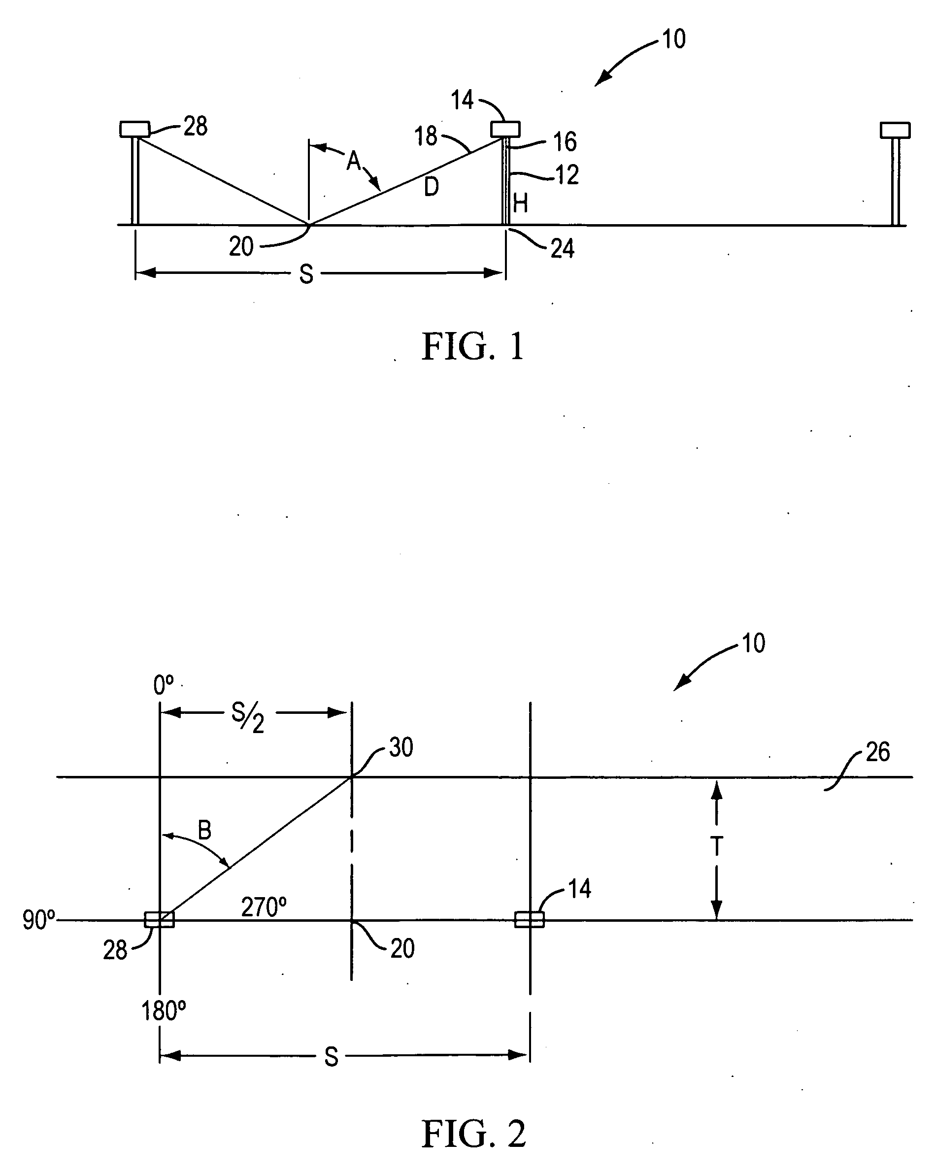
[0074]FIG. 1 in combination with FIG. 2, is a representation of a group of three light poles, generally 10, that show one environment, an outdoor lightin...


PUM


Abstract

A lens is provided for use with a solid-state light-emitting device, typically a light-emitting diode. The lens may be used in luminaries for roadway lighting and other applications. In one embodiment the lens includes a conical structure proximate the light-emitting source of the light-emitting device.

Description

BACKGROUND OF THE INVENTION[0001]1. Field of the Invention[0002]This invention is related to a high performance lens for use in combination with a solid-state light-emitting device, typically a light-emitting diode (“LED”) and to the optics of the lenses of solid-state light-emitting devices used in luminaries for roadway lighting and other applications where light delivery is selectively and passively accomplished.[0003]In one embodiment of the invention the lens for use with a solid-state light-emitting device includes an upstanding conical structure generally directly above the light-emitting source of the light-emitting device.[0004]2. Description of the State of the Art[0005]It is increasingly common to adopt new light sources for use in all types of lighting situations. Incandescent lamps that have been widely used in the commercial and residential lighting situations are being replaced by compact fluorescent lamps as the compact fluorescent lamps are more energy efficient tha...

Claims


Application Information

Patent Timeline
Patent Type & Authority Applications(United States)
IPC IPC(8): F21V5/04G02B13/18
CPCF21S8/08F21V5/04G02B19/0061F21Y2101/02G02B19/0028F21V7/0091F21Y2115/10
Inventor LEWIN, IANO'FARRELL, JOHN K.
Owner LEWIN IAN
Why Eureka
Try Eureka