
Optical irradiation device

a technology of optical irradiation and optical beam, which is applied in the direction of optical radiation measurement, lighting support devices, boring tools, etc., can solve the problems of reducing the efficiency of dental treatment delivered, and achieve the effect of improving the level of irradian

Inactive Publication Date: 2010-03-25
SIGNIFY HLDG BV
View PDF101 Cites 6 Cited by
  • Summary
  • Abstract
  • Description
  • Claims
  • Application Information

AI Technical Summary

Benefits of technology

The present invention provides an optical irradiation device that uses LEDs and has the benefits of compactness, portability, ruggedness, and long life. The device also produces improved levels of irradiance at and above 300 mW / sq. cm. The invention includes LEDs clustered in the device by forming shaped facets on adjacent LEDs, a tapered light guide, an optical irradiation device employing LEDs and a heat pipe, and a tapered light guide with multiple guides arranged in series. The invention also includes a heat pipe with a divided annular space containing a material that serves to absorb heat by a phase change. The invention allows for improved cooling of LEDs and reduces the power required to drive the device and the heat generated by it. The more effective packing density produces an overall increase in irradiance. The invention also includes a central LED and rings of LEDs arranged around it, with the LEDs abutting each other and possibly with inwardly diverted faces abutting respective outwardly directed faces of the LEDs of the inner ring.

Problems solved by technology

However, there is a problem in producing a sufficient level of irradiance even with a clustered array of LEDs, to cure the known dental polymers in the recommended time.
At the lower levels of irradiance available generally below 300 mW / sq. cm, longer curing times have to be allowed, which reduces the efficiency of the dental treatment delivered.

Method used


Image

  • Optical irradiation device
  • Optical irradiation device
  • Optical irradiation device

Examples


second embodiment

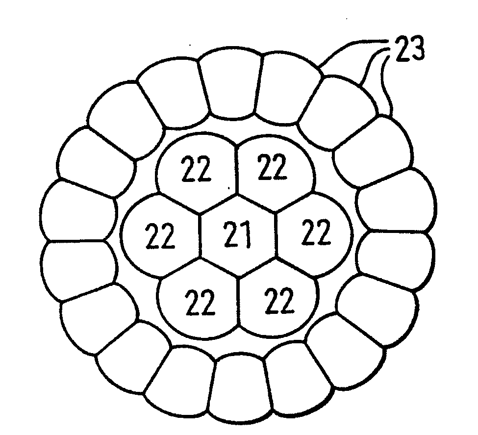
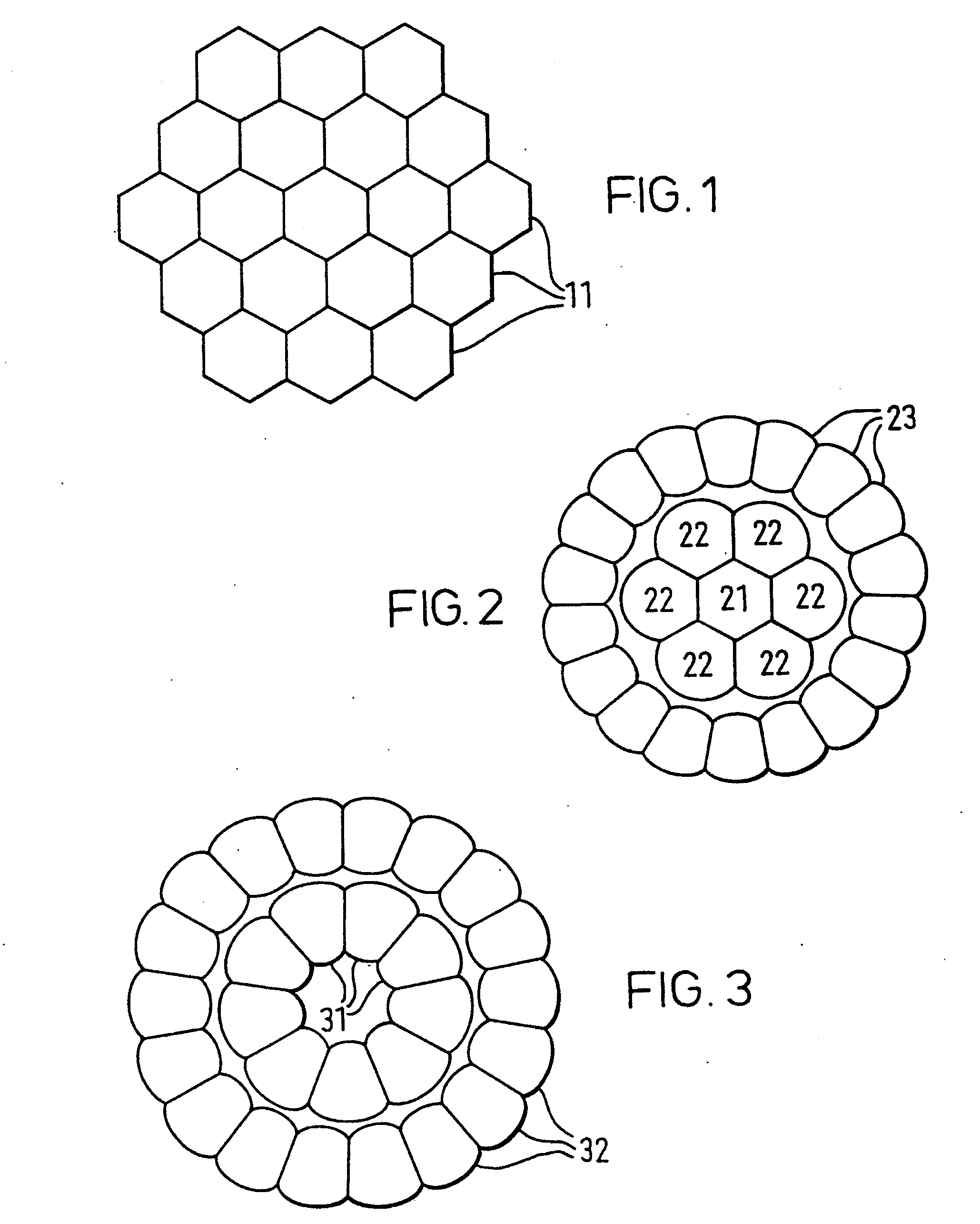
[0024]In the invention illustrated in FIG. 2, a central LED 21 of hexagonal cross-section has facets which abut adjacent facets of six LEDs 22 in a first ring of LEDs with radially extending side facets that allow adjacent LEDs in the ring to abut one another. A second ring of LEDs 23 is arranged around the first ring of LEDs, and these LEDs 23 have radially extending side facets that allow adjacent LEDs in the ring to abut one another.

third embodiment

[0025]In the invention shown in FIG. 3, an inner ring of nine LEDs 31 in a first ring is contained within a second ring of LEDs 32, and radially extending side facets of the LEDs in both rings allow adjacent LEDs in each ring to abut one another.

[0026]Both the second embodiment of FIG. 2 and the third embodiment of FIG. 3 may be modified by the addition of one or more further concentric rings of LEDs. Also, the circumferential facets of the LEDs of each ring may be shaped to abut similarly shaped circumferential facets of the adjacent ring of LEDs.

[0027]In yet another embodiment, the central group of LEDs 21,22 of FIG. 2 may be replaced by the same number of LEDs in a honeycomb cluster. Yet another embodiment may consist of the single ring of LEDs 31 shown in FIG. 3. It will be appreciated in all three illustrated embodiments, the LEDs are mounted in a substantially flat plane.

[0028]In modifying the conventional optical sphere shape of the outer plastics envelope of a LED care has t...


PUM


Abstract

An optical irradiation device incorporating a cluster of LEDs arranged so that shaped facets of adjacent LEDs come together to increase the packing density of LEDs in the cluster. A light guide collects light emitted by the LEDs. Two or more light guides and LED clusters may be arranged in series to produce a single light beam. A heat pipe is provided to conduct heat away from the LEDs. The heat pipe may be annular and contain an inner storage space for batteries or the like.

Description

RELATED APPLICATIONS[0001]This application is a divisional of U.S. patent application Ser. No. 09 / 509,433 filed May 30, 2000, entitled “OPTICAL IRRADIATION DEVICE HAVING LED AND HEAT PIPE”; which application is a 371 of PCT / GB98 / 02905 filed Sep. 25, 1998, entitled “OPTICAL IRRADIATION DEVICE and claims the benefit of priority to United Kingdom Patent Application Serial No. 9720443.2 filed Sep. 25, 1997, entitled “DENTAL CURING” and United Kingdom Patent Application Serial No. 9806046.0 filed Mar. 20, 1998, entitled “DENTAL CURING.” These prior applications are incorporated herein by reference in their entirety.TECHNICAL FIELD[0002]This invention relates to an optical irradiation device, especially a compact portable irradiation device suitable for use as a light polymerisation source.[0003]It has already been proposed to use light-emitting diodes LEDs in a hand held device to produce a focused beam of light to cure dental materials. Blue light at a peak wavelength of about 470 nm is...

Claims


Application Information

Patent Timeline
Patent Type & Authority Applications(United States)
IPC IPC(8): H01L33/00F21S4/00F21V1/00F21L4/00A61C13/15A61N5/06G02B6/42H01L25/13
CPCA61C19/004A61N5/0601G02B6/4298A61N2005/0652A61N5/062Y10S362/80
Inventor MILLS, ROBIN WALTERJANDT, KLAUS DIETER
Owner SIGNIFY HLDG BV
Learn More