Method for operating one-time programmable read-only memory

a one-time programmable, read-only memory technology, applied in the field of memory operation, to achieve the effect of effectively storing data

Inactive Publication Date: 2010-03-25
EMEMORY TECH INC
View PDF8 Cites 9 Cited by
  • Summary
  • Abstract
  • Description
  • Claims
  • Application Information

AI Technical Summary

Benefits of technology

[0007]In view of the foregoing, the present invention is directed to a method for operating an OTP-ROM which is novel and is able to store data effectively.
[0008]The present invention is further directed to a method for operating an OTP-ROM which is capable of preventing data errors when performing a read function.
[0014]Moreover, with a select gate, the OTP-ROM of the present invention can effectively control currents entering the OTP-ROM, so as to avoid the unnecessary breakdown effect and to properly store the data. Moreover, the select gate is capable of preventing data errors when performing the read function on the OTP-ROM.

Problems solved by technology

As a result, it is an essential issue for semiconductor manufacturers to satisfy said demands by fabricating the inexpensive memories with great storage capacity.

Method used


Image

  • Method for operating one-time programmable read-only memory
  • Method for operating one-time programmable read-only memory
  • Method for operating one-time programmable read-only memory

Examples


first embodiment

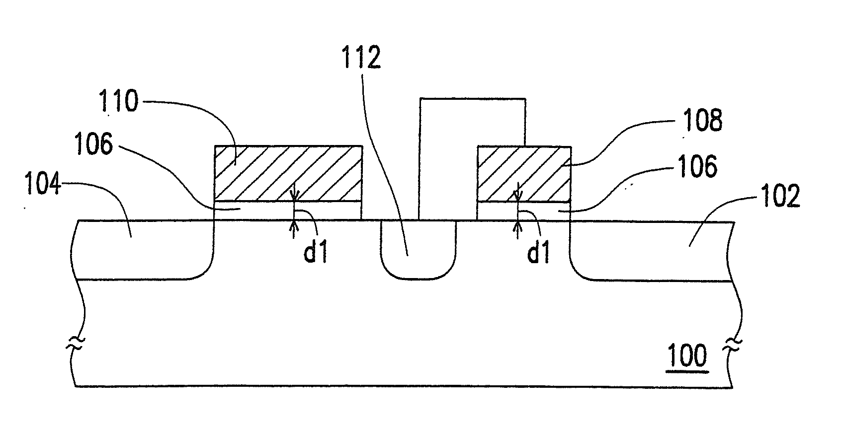
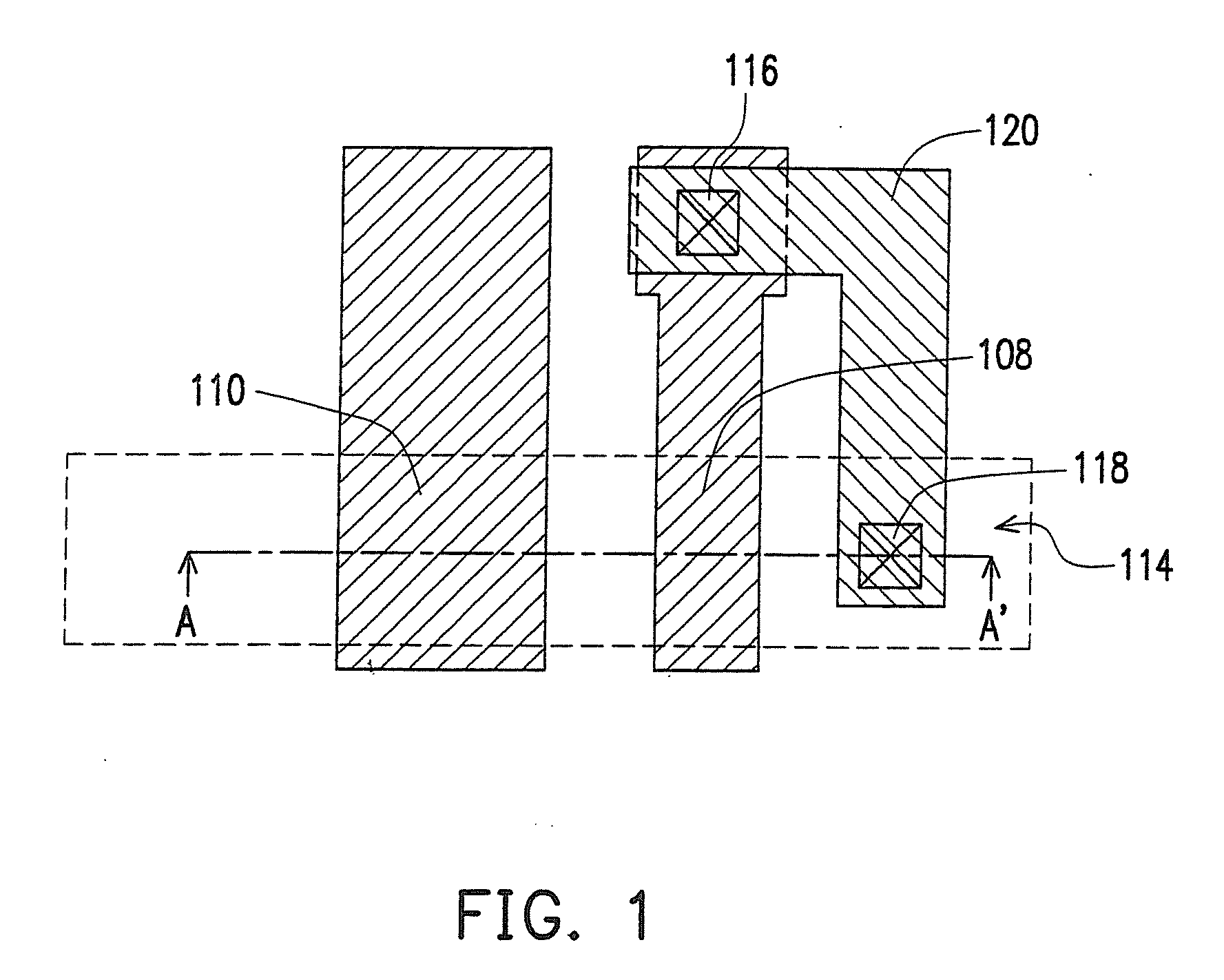
[0020]FIG. 1 is a top view of an OTP-ROM according to the present invention. FIG. 2 is a cross-sectional view along line A-A' in FIG. 1.

[0021]Referring to FIGS. 1 and 2, the OTP-ROM includes a substrate 100, a doped region 102, a doped region 104, a gate dielectric layer 106, a gate 108, and a gate 110. The OTP-ROM is an N-type memory cell or a P-type memory cell. In the present embodiment, the OTP-ROM is the N-type memory cell, for example.

[0022]The substrate 100 is of a first conductive type having an N-type dopant or a P-type dopant. In the present embodiment, the substrate 100 is the P-type substrate, for example.

[0023]The doped regions 102 and 104 are of a second conductive type and are separately disposed in the substrate 100 within an active region 114. The doped region 102 serves as a source line, while the doped region 104 serves as a bit line. The doped regions 102 and 104 are formed through performing an ion implantation process, for example. Here, the second conductive t...

second embodiment

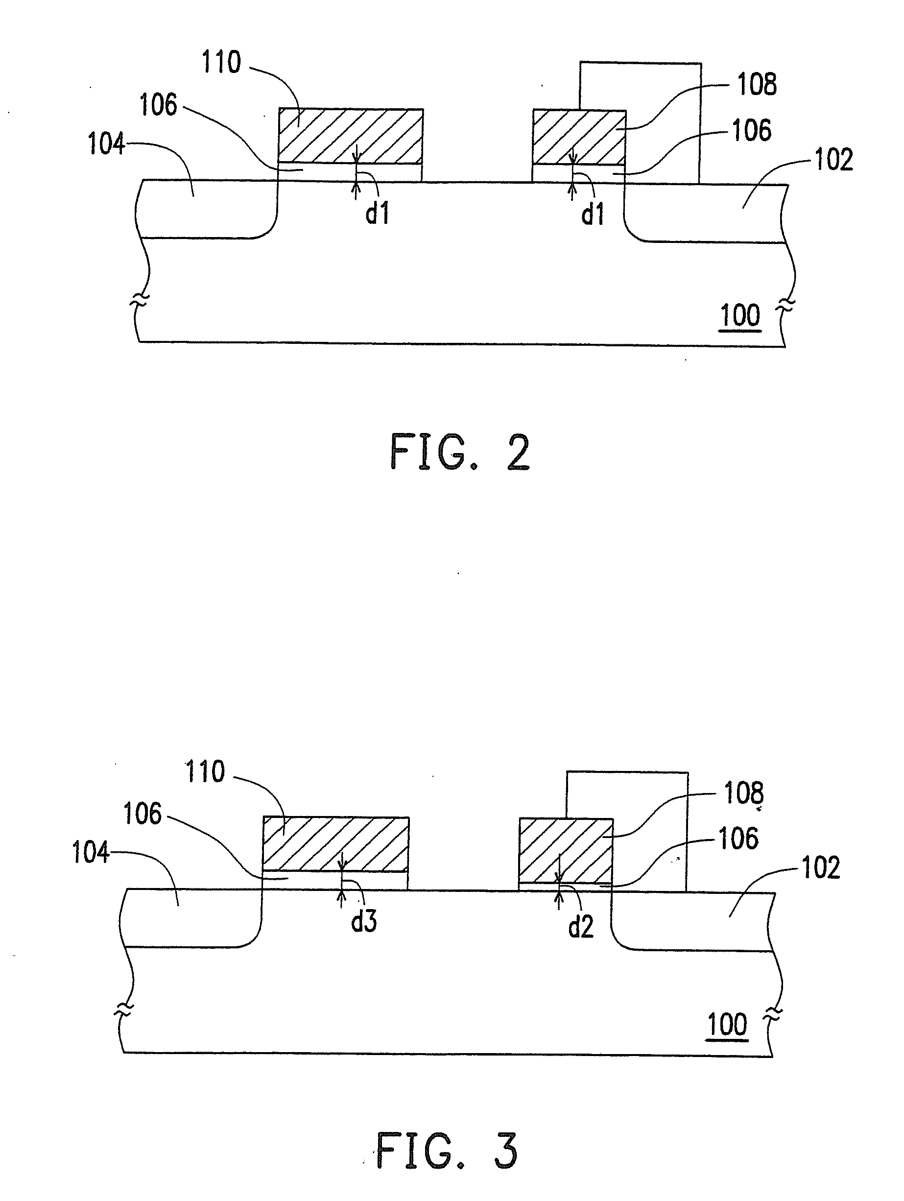
[0034]Referring to FIG. 3, in the second embodiment, the gate dielectric layer 106 has a thickness d2 and a thickness d3. The gate dielectric layer 106 having the thickness d2 is disposed below the gate 108, while the gate dielectric layer 106 having the thickness d3 is below the gate 110. Here, the thickness d2 is less than the thickness d3.

third embodiment

[0035]Referring to FIG. 4, in the third embodiment, the gate dielectric layer 106 disposed below the gate 108 has a thickness d4 and a thickness d5. The gate dielectric layer 106 having the thickness d4 is adjacent to the doped region 102, while the gate dielectric layer 106 having the thickness d5 is adjacent to the doped region 104. Here, the thickness d4 is greater than the thickness d5. Besides, the gate dielectric layer 106 disposed below the gate 110 has the thickness d5, for example.


PUM


Abstract

A method for operating a one-time programmable read-only memory (OTP-ROM) is provided. The OTP-ROM comprises a first gate and a second gate respectively disposed on a gate dielectric layer between a first doped region and a second doped region on a substrate, wherein the first gate is adjacent to the first doped region and coupled to the first doped region, the second gate is adjacent to the second doped region, the first gate is electrically coupled grounded, and the OTP-ROM is programmed through a breakdown effect. The method comprises a step of programming the OTP-ROM under the conditions that a voltage of the second doped region is higher than a voltage of the first doped region, the voltage of the second gate is higher than a threshold voltage to pass the voltage of the second doped region, and the first doped region and the substrate are at a reference voltage.

Description

CROSS-REFERENCE TO RELATED APPLICATION[0001]This application claims the priority benefit of U.S. application Ser. No. 11 / 956,633, filed on Dec. 14, 2007, which claims the priority benefit of U.S. provisional application Ser. No. 60 / 940,666, filed on May 29, 2007. The entirety of each of the above-mentioned patent applications is hereby incorporated by reference herein and made a part of this specification.BACKGROUND OF THE INVENTION[0002]1. Field of the Invention[0003]The present invention relates to a method for operating a memory, and more particularly to a method for operating a one-time programmable read-only memory (OTP-ROM).[0004]2. Description of Related Art[0005]As functions of microprocessors continue to be expanded, an amount of computation in a given software program increases exponentially, and demands for memories are also increasing. As a result, it is an essential issue for semiconductor manufacturers to satisfy said demands by fabricating the inexpensive memories wit...

Claims


Application Information

Patent Timeline
Patent Type & Authority Applications(United States)
IPC IPC(8): G11C17/08
CPCG11C17/16H01L27/11206H01L27/112G11C17/18H10B20/20H10B20/00
Inventor LAI, TSUNG-MUHUANG, SHAO-CHANGCHING, WEN-HAOLU, CHUN-HUNGWANG, SHIH-CHENHO, MING-CHOU
Owner EMEMORY TECH INC
Why Eureka
Try Eureka