Devices and methods for assessing a sample's temperature exposure history

a technology of temperature exposure history and device, which is applied in the direction of instruments, thermometers using mean/integrated values, heat measurement, etc., can solve the problems of excessive heat damage, variable products and components may be damaged, and damage to turbine blades

Active Publication Date: 2010-03-25
LAWLESS JOHN L +1
View PDF13 Cites 8 Cited by
  • Summary
  • Abstract
  • Description
  • Claims
  • Application Information

AI Technical Summary

Problems solved by technology

Various products and components may be damaged when exposed to temperatures above a critical level.
Turbine blades may be damaged when exposed to high peak temperatures, but the damage caused by excessive heat may not be readily apparent from casual observation.
As turbine blades are often put to use at high speeds, the consequences associated with the blades' failure in operation may be catastrophic.
However, there are a number of disadvantages associated with taking hardness measurements on the indicators to measure the temperature exposure history of the products and parts.
For example, hardness measurement are considered destructive or semi-destructive, because once a measurement has been made it cannot be repeated over exactly the same spot.
Other known temperature sensors do not generally provide a persistent record of temporary temperature deviations.
While conventional temperature sensors such as thermometers or thermocouples provide a continuous indication of the temperature of the material at any particular instant in time, they do not provide a permanent indication of out-of-range temperatures.
One problem with such techniques is that the microcontroller may not be able to withstand the same temperatures as the sensor and must be isolated from the environment whose temperature is being measured by the sensor.
Another problem associated with such techniques is that the microcontrollers and accompanying electronics must be continuously powered when in use.
Another problem, common to thermocouples, thermistors, and resistance temperature detectors, is that they must be connected to the microcontroller, or to an accessory device, by extension wires which complicate the installation and pose durability problems
However, this method suffers from drawbacks similar to those associated with the above-described microcontroller methods.
The interaction of ionizing radiation with a nonmetallic material may result in charge-carrier redistribution within the material.
Some part of the redistributed charge carrier population may become trapped at defects in the material.
A fraction of the released charge carriers will recombine, which results in luminescence.
If the badge has been exposed to ionizing radiation, some part of the charge carrier population will have become trapped.

Method used


Image

  • Devices and methods for assessing a sample's  temperature exposure history
  • Devices and methods for assessing a sample's  temperature exposure history
  • Devices and methods for assessing a sample's  temperature exposure history

Examples


Embodiment Construction

Definitions and Overview

[0029]Before describing the invention in detail, it must be noted that, as used in this specification and the appended claims, the singular forms “a,”“an,” and “the” include plural referents unless the context clearly dictates otherwise. Thus, for example, reference to “a charge-carrier trap” includes one or more charge-carrier traps, reference to “a trap-releasing temperature” includes a single trap-releasing temperature as well as a range of trap-releasing temperatures and the like.

[0030]In describing and claiming the present invention, the following terminology will be used in accordance with the definitions set out below.

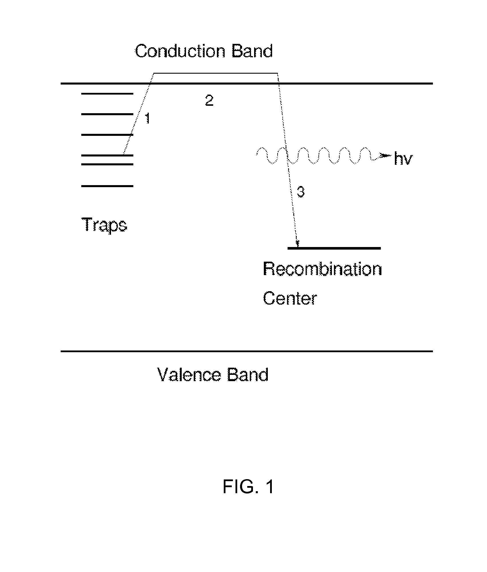
[0031]The term “band” as used herein in its ordinary solid-state physic sense and refer to a range of very closely spaced electronic energy levels in solids, the distribution and nature of which determine the electronic properties of a material. For example, the term “valence band” refers to electronic states with the highest range of ele...


PUM


Abstract

Device and methods are provided for assessing a temperature exposure history of a sample that is comprised of a nonmetallic material. To assess the temperature exposure history, the pre-exposure and post-exposure electronic states of the sample are compared. Changes in the electronic state of the sample are indicative of the temperature exposure history.

Description

STATEMENT REGARDING FEDERALLY SPONSORED RESEARCH OR DEVELOPMENT[0001]This invention was made with Government support under Contract No. F29601-02-C-0137 awarded by the U.S. Air Force. The Government has certain rights in the invention.BACKGROUND[0002]1. Technical Field[0003]The present invention generally relates to devices and methods for assessing a temperature exposure history of a sample, e.g., the maximum temperature that the sample has attained since the last time it was prepared for use. In particular, the invention relates to such devices and methods that assess the temperature experienced by a nonmetallic sample comprising a nonmetallic material of an optionally disordered and / or multicrystalline microstructure by detecting for changes in the electronic state of the material.[0004]2. Related Art[0005]Various products and components may be damaged when exposed to temperatures above a critical level. For example, in the course of normal operation, turbine blades may be expose...

Claims


Application Information

Patent Timeline
Patent Type & Authority Applications(United States)
IPC IPC(8): G01K3/00
CPCG01K11/20G01K3/04
Inventor LAWLESS, JOHN L.MOFFAT, ROBERT J.
Owner LAWLESS JOHN L
Why Eureka
Try Eureka