Sample observation method and observation device

Inactive Publication Date: 2007-03-01
OSAKA UNIV
View PDF5 Cites 5 Cited by
  • Summary
  • Abstract
  • Description
  • Claims
  • Application Information

AI Technical Summary

Benefits of technology

[0014] A sample observation method of the present invention detects variation in surface potential of a sample due to variation in the Hall effect based on variation in an applied current or applied magnetic field to the sample.
[0015] According to the above sample observation method of the present invention, the variation in surface potential (surface Hall potential) of the sample due to the Hall effect generated in the sample can be observed. The surface Hall potential is generated by the Lorentz force in the sample thickness direction acting on carriers in the sample to create an electric field (the Hall field) in the sample thickness direction. The surface Hall potential varies depending on variation in the Hall field and variation in thickness of the sample. Further, the Hall field varies depending on internal structures or electronic states of the sample. On the other hand, local surface potentials of the sample can be observed with existing devices, for example, Kelvin Probe Force microscopes. Therefore, information on local internal structures, electronic states, etc. of the sample can be obtained by observation of local surface Hall potentials of the sample.
[0016] S

Problems solved by technology

However, the electronic material observation methods using scanning probe microscopy as described above are a surface-sensitive approach in principle, and therefore can provide information only on surfaces or surface vicinities of the electronic materials.
However, the potential difference due to the Hall effect m

Method used


Image

  • Sample observation method and observation device
  • Sample observation method and observation device
  • Sample observation method and observation device

Examples


Embodiment Construction

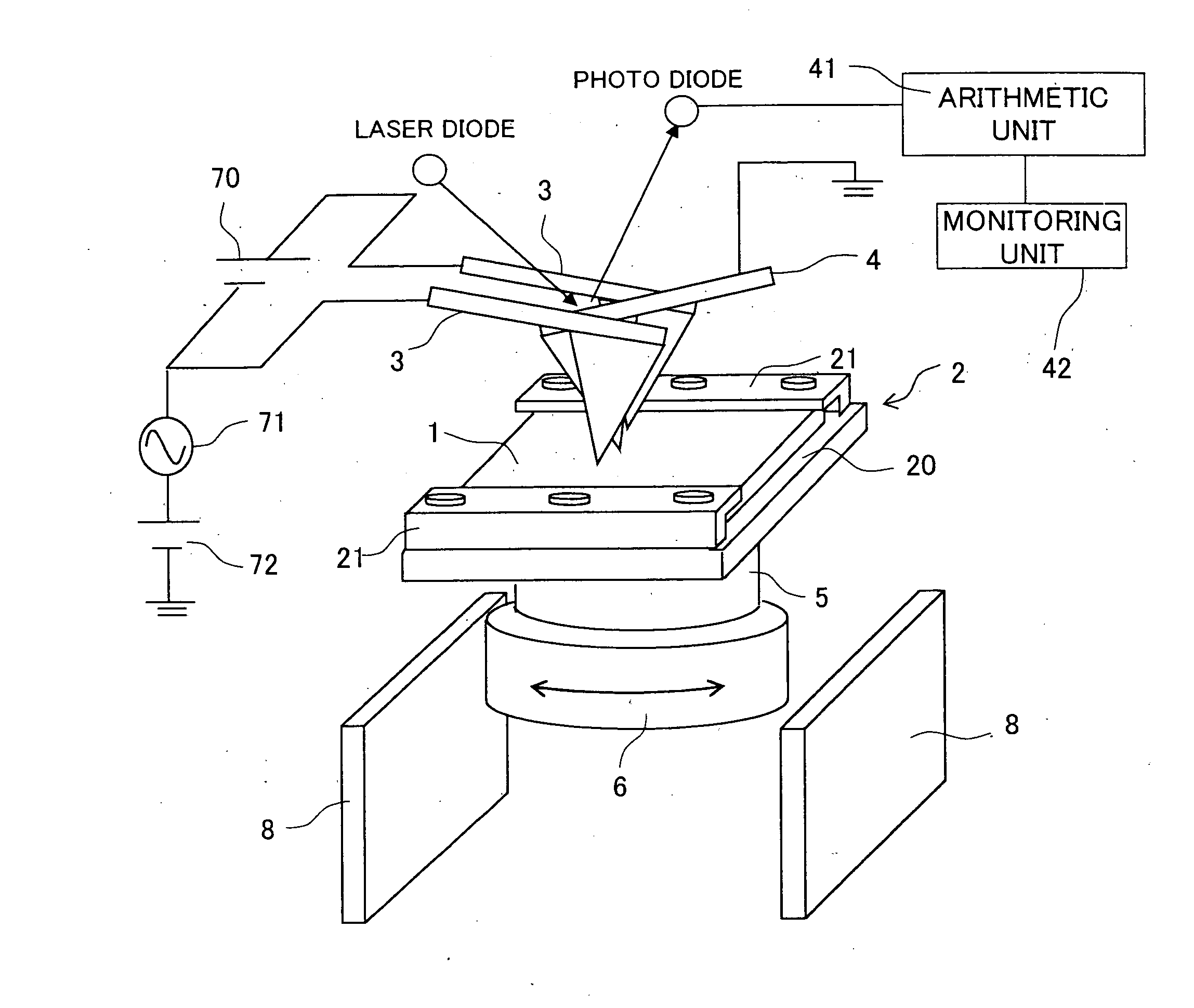
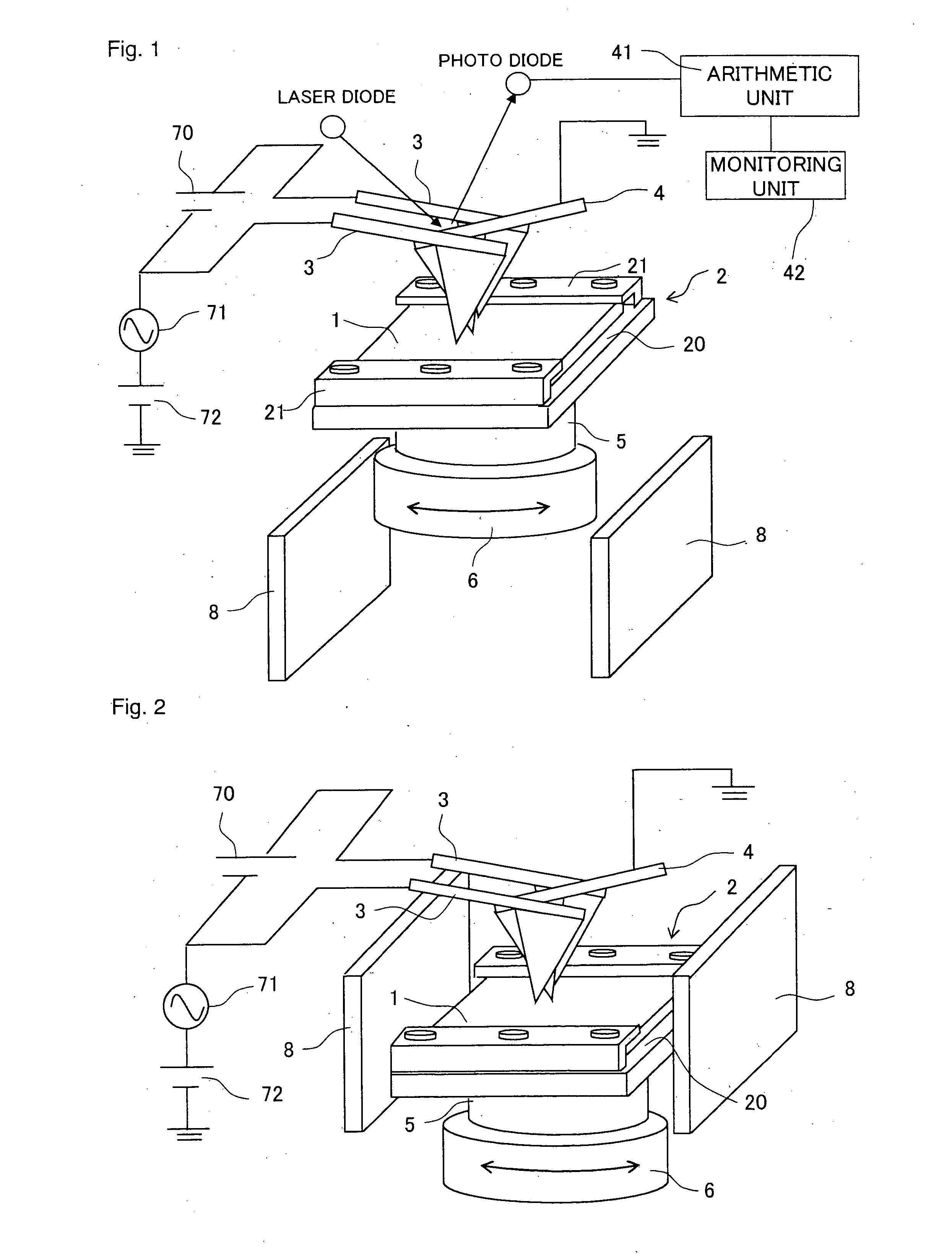
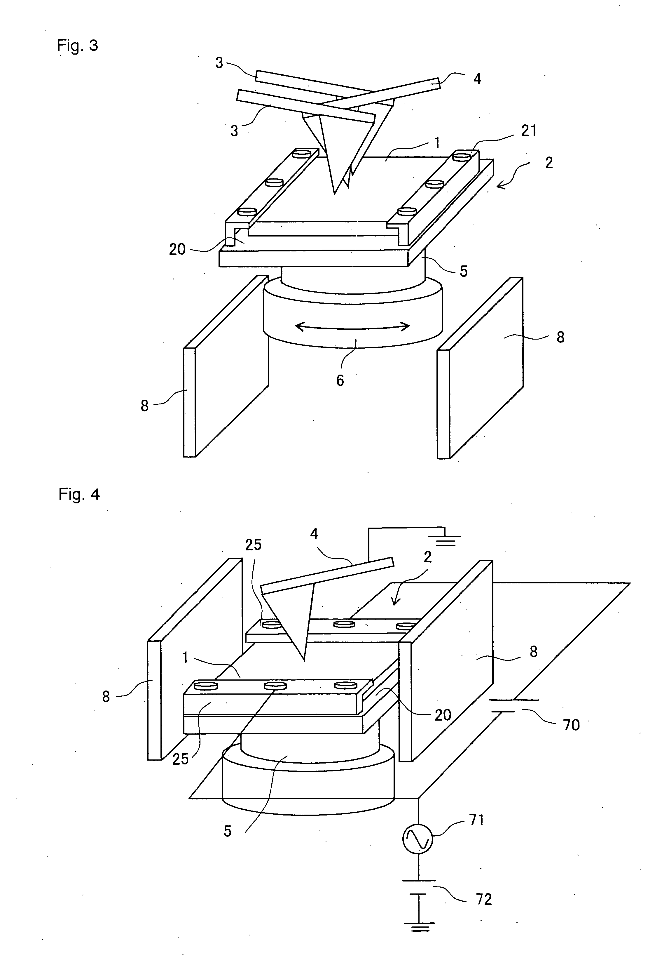
[0061] Embodiments of the present invention will be specifically described below with reference to the drawings. FIG. 1 shows a first embodiment of a sample observation device of the present invention. The observation device of the first embodiment includes a scanning probe microscope for measuring a local surface potential of a sample 1 by Kelvin Probe Force Microscopy, and a current / magnetic field application unit for applying a current and magnetic field to the sample 1.

[0062] The scanning probe microscope includes a stage 2 for fixing the sample 1 and a conductive cantilever 4 as a probe for measuring the surface potential. The stage 2 is made of an insulating material such as Macor, and includes a pair of holding plates 21, 21 arranged at opposite ends of a flat portion 20 for holding the sample 1. Opposite ends of the sample 1 are held between the flat portion 20 and the pair of holding plates 21, 21 to fix the sample 1 on the stage 2. The stage 2 is placed on a rotary stage ...


PUM


Abstract

A sample observation method and sample observation device of the present invention are for observing variation in surface potential of a sample due to variation in the Hall effect based on variation in an applied current or applied magnetic field to the sample, and allow the variation in the Hall effect generated in the sample to be locally observed. The Hall effect varies depending on internal structures, electronic states, etc. of the sample. The variation in surface potential due to variation in the Hall effect includes information on internal structures, electronic states, etc. of the sample.

Description

[0001] This application claims priority of U.S. Provisional Application for Patent Ser. No. 60 / 711,696, filed Aug. 29, 2005, which is incorporated herein by reference.BACKGROUND OF THE INVENTION [0002] 1. Field of the Invention [0003] The present invention relates to a sample observation method and observation device for observing microscopic internal structures, electronic states, etc. of samples including various materials. [0004] 2. Description of Related Art [0005] For higher-performance next-generation electronic devices, it is essential to establish a technique that can measure / evaluate microscopic structures and electronic states inside electronic materials. For example, next-generation ultra-highly integrated semiconductor devices demand a technique for evaluating / controlling source-drain impurity profiles of Metal-Oxide-Semiconductor Field Effect Transistors (MOSFET) on the nanoscale. In order to realize further higher-performance solar cell devices and Thin Film Transistor...

Claims


Application Information

Patent Timeline
IPC IPC(8): G01B7/30
CPCG01Q60/30B82Y35/00
Inventor ARIMA, KENTA
Owner OSAKA UNIV
Why Eureka
Try Eureka