X-ray tube with multiple electron sources and common electron deflection unit

a technology of electron deflection unit and x-ray tube, which is applied in the field of generating x-rays by means of x-ray tubes, can solve problems such as reconstruction artifacts and reconstruction problems, and achieve the effects of enhancing spatial resolution and spatial resolution of the x-ray system

Inactive Publication Date: 2010-03-25
KONINKLIJKE PHILIPS ELECTRONICS NV
View PDF9 Cites 28 Cited by
  • Summary
  • Abstract
  • Description
  • Claims
  • Application Information

AI Technical Summary

Benefits of technology

[0043]One may take benefit from illuminating an object under examination with two different sets of X-rays, whereby the two X-ray sets penetrate the object with at least slightly different illumination angles. When using a detector array for sensing the X-rays having traversed the object, one can design the X-ray system such that the so-called interleaving technique is applied. Thereby, neighboring X-rays originating from different focal spots are separated from each other by a distance being half of the distance between neighboring X-rays in the case when only one focal spot is used. This has the advantage that when two X-ray acquisitions being assigned to the two focal spots are combined in an appropriate manner, the spatial resolution of the X-ray system may be enhanced. Under op...

Problems solved by technology

However, the use of an X-ray tube comprising only a single focal spot sometimes causes reconstruction problems in particular when large objects ...

Method used


Image

  • X-ray tube with multiple electron sources and common electron deflection unit
  • X-ray tube with multiple electron sources and common electron deflection unit
  • X-ray tube with multiple electron sources and common electron deflection unit

Examples


Embodiment Construction

[0054]The illustration in the drawing is schematic. It is noted that in different figures, similar or identical elements are provided with the same reference signs or with reference signs, which are different from the corresponding reference signs only within the first digit.

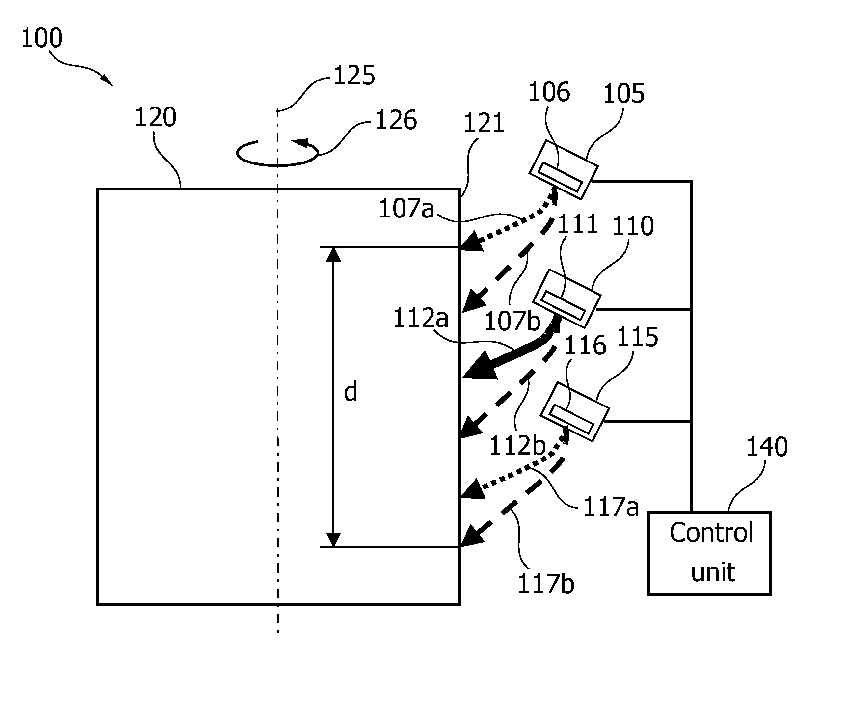
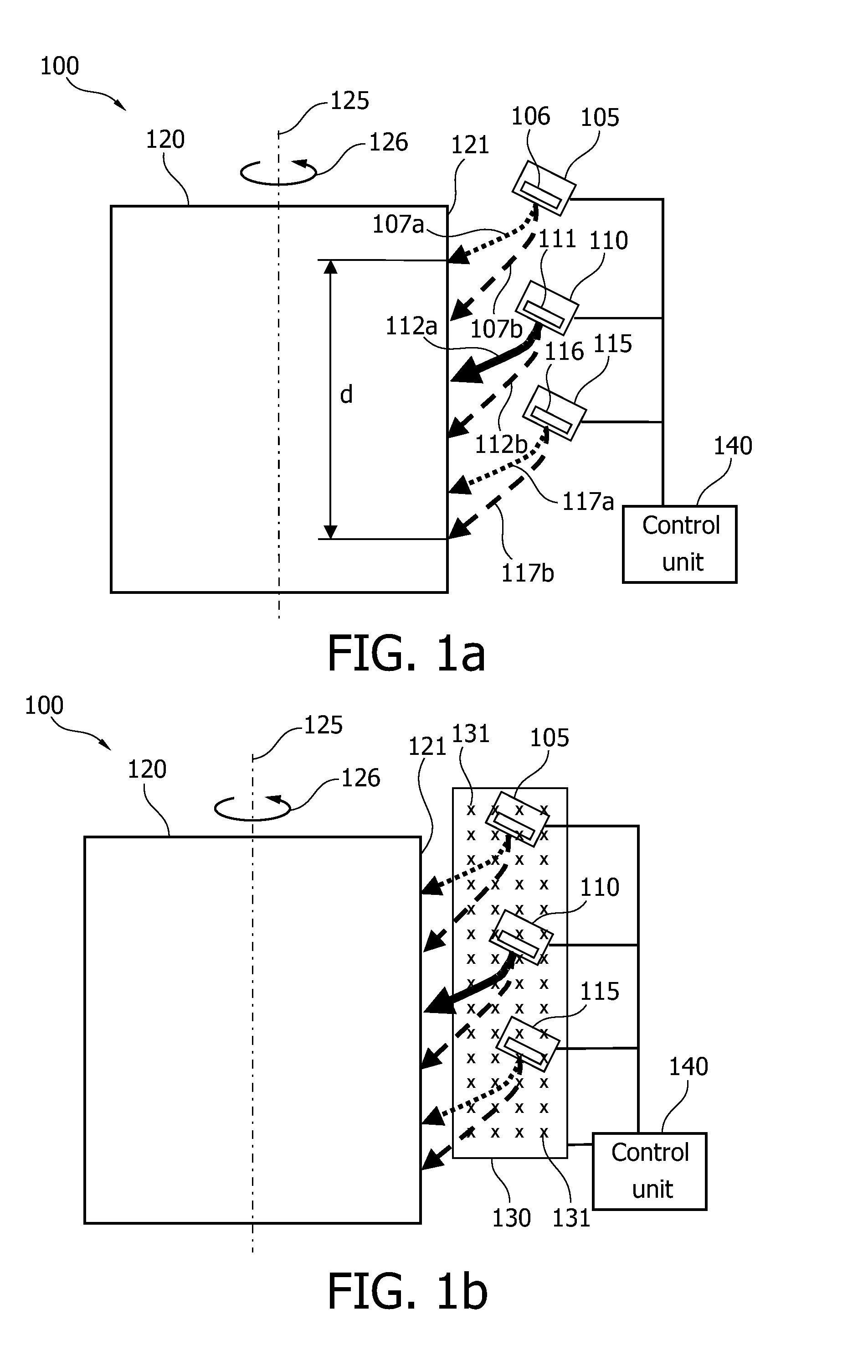
[0055]FIG. 1a shows a side view of a multi electron beam X-ray tube 100. The X-ray tube 100 comprises a linear array of three electron sources, a first electron source 105, a second electron source 110 and a third electron source 115. The first electron source 105 comprises an electron emitter filament 106, the second electron source 110 comprises an electron emitter 111 and the third electron source 115 comprises an electron emitter 116. Each of the electron sources 105, 110, 115 is adapted to generate an electron beam projecting along a beam path towards an anode 120.

[0056]A common magnetic deflection unit, which is not depicted in FIG. 1a, is used to deflect the generated electron beams 105, 110, 115. Dependi...


PUM


Abstract

It is described an X-ray tube (100, 200) for moving a focal spot within a wide range. The X-ray tube (100, 200) comprises a first electron source (105), which is adapted to generate a first electron beam projecting along a first beam path (107a, 107b), a second electron source (110), which is adapted to generate a second electron beam projecting along a second beam path (112a, 112b) and an anode (120), which is arranged within the first beam path (107a, 107b) and within the second beam path (112a, 112b) such that on a surface (121) of the anode (120) the first electron beam (307a) generates a first focal spot (308) and the second electron beam (412a) generates a second focal spot (413). The X-ray tube (100, 200) further comprises a common deflection unit (130, 330, 430), which is adapted to deflect the first (307a) and the second electron beam (412a), such that the positions of the first (308) and the second focal spot (413) is shifted. The electron sources (105, 110) may be arranged within a linear array allowing for a simple mechanical support of the X-ray sources.

Description

FIELD OF INVENTION[0001]The present invention relates to the field of generating X-rays by means of X-ray tubes. In particular, the present invention relates to an X-ray tube, which is adapted to generate at least two X-ray beams originating from at least two different focal spot positions. Thereby, the at least two X-ray beams may be activated simultaneously or preferably in an alternating manner. Such types of X-ray tubes are called multiple focal spot X-ray tubes.[0002]The present invention further relates to an X-ray system, in particular to a medical X-ray imaging system, wherein the X-ray system comprises an X-ray tube as mentioned above.[0003]Further, the present invention relates to a method for generating X-rays, which are in particular used for medical X-ray imaging. The X-rays are generated by means of an X-ray tube as mentioned above.ART BACKGROUND[0004]Computed tomography (CT) is a standard imaging technique for radiology diagnosis. However, the use of an X-ray tube com...

Claims


Application Information

Patent Timeline
IPC IPC(8): H01J35/30H01J35/14H01J35/08A61B6/00
CPCH01J35/06H01J2235/068H01J35/14H01J35/153
Inventor BEHLING, ROLF KARLOTTOCARLSON, GERALD JAMES
Owner KONINKLIJKE PHILIPS ELECTRONICS NV
Why Eureka
Try Eureka