Tapered roller bearing

a tapered roller and bearing technology, applied in the direction of rolling contact bearings, shafts and bearings, rotary bearings, etc., can solve the problems of limited increase in load-carrying capacity, and achieve the effects of extending the life, improving load-carrying capacity, and increasing the axial center length of the tapered roller

Inactive Publication Date: 2010-03-25
NTN CORP
View PDF6 Cites 14 Cited by
  • Summary
  • Abstract
  • Description
  • Claims
  • Application Information

AI Technical Summary

Benefits of technology

[0022]In the tapered roller bearing of the present invention, the shoulder section on the small-diameter side of the inner roller that is conventionally present is omitted. Therefore, the tapered roller bearing can be made lighter by an amount corresponding to the omitted shoulder section. Moreover, the raceway is increased by an amount corresponding to the omitted shoulder section and relief section on the small-diameter side. As a result, the axial center length of the tapered rollers can be increased. The load-carrying capacity can be improved, and lifetime can be extended. Because the engaging section of the cage engages with the shoulder section of the inner ring, the tapered rollers can be prevented from falling towards the small-end side. The inner ring, the tapered rollers, and the cage can be handled as an assembly (an assembled unit). Assembly (manufacturability) of the overall bearing can be enhanced.
[0023]Moreover, when the cage that is made of resin is formed, the cage can be formed using a mold without being affected by the engaging section. Therefore, manufacturability can be enhanced. The tapered roller bearing can be stably manufactured with certainty. Because the cage is made of resin, abrasion powder caused by abrasion is not produced. Therefore, deterioration of lubrication caused by the abrasion powder does not occur. Lifetime can be extended.
[0024]As a result of the engaging section locking onto the notched section on the shoulder section, engagement of the engaging section to the shoulder section side can be improved. Moreover, the engaging section can be prevented from projecting in an outward axial direction on the large-diameter side of the inner ring. As a result, the tapered roller bearing can be made more compact. The depth of the notched section to which the engaging section engages can be shallow. Deterioration in strength of the shoulder section can be prevented. As a result, insufficient strength of the roller bearing due to the shoulder section can be prevented, and the tapered rollers can be stably received.
[0025]Compared to a cage made of an iron plate, the resin cage is lighter. The resin cage is also self-lubricating and has a low coefficient of friction. Therefore, together with the effects of a lubricant present within the bearing, the resin cage can prevent abrasion caused by contact with the outer ring. Moreover, because the resin cage is self-lubricating and has a small coefficient of friction, the resin cage is suitable for reducing torque loss during bearing start-up and wear in the cage.

Problems solved by technology

In this way, conventionally, the increase in load-carrying capacity is limited.

Method used


Image

  • Tapered roller bearing
  • Tapered roller bearing
  • Tapered roller bearing

Examples


second embodiment

[0050]Next, a double-row tapered roller bearing will be described with reference to FIG. 4. In the double-row tapered roller bearing, thickness of a small diameter ring-shaped section of a cage is reduced. The double-row tapered roller bearing is particularly suitable for use in a power transmission system (such as a differential) of an automobile. The tapered roller bearing includes inner rings 2A and 2B, outer rings 1A and 1B, a plurality of tapered rollers 23A and 23B, and cages 24A and 24B. The inner rings 2A and 2B are fixed onto a shaft (not shown), such as a drive shaft or a propeller shaft, and have conical raceways 5a and 5b on the outer circumference. The outer rings 1A and 1B are fixed onto a housing (not shown) and have conical raceways 6a and 6b on the inner circumference. The tapered rollers 23A and 23B are interposed between the raceways of the inner rings 2A and 2B, and the outer rings 1A and 1B. The cages 24A and 24B hold the plurality of tapered rollers 23A and 23...
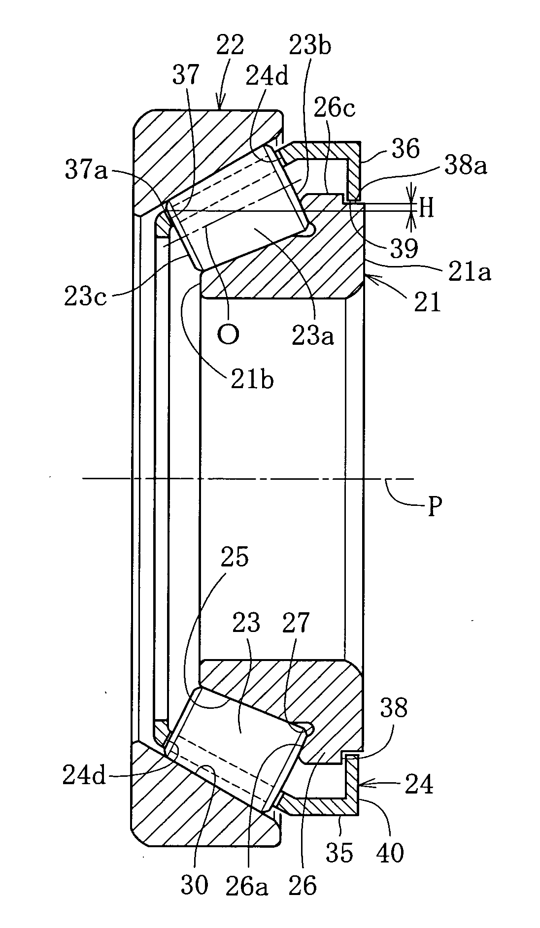
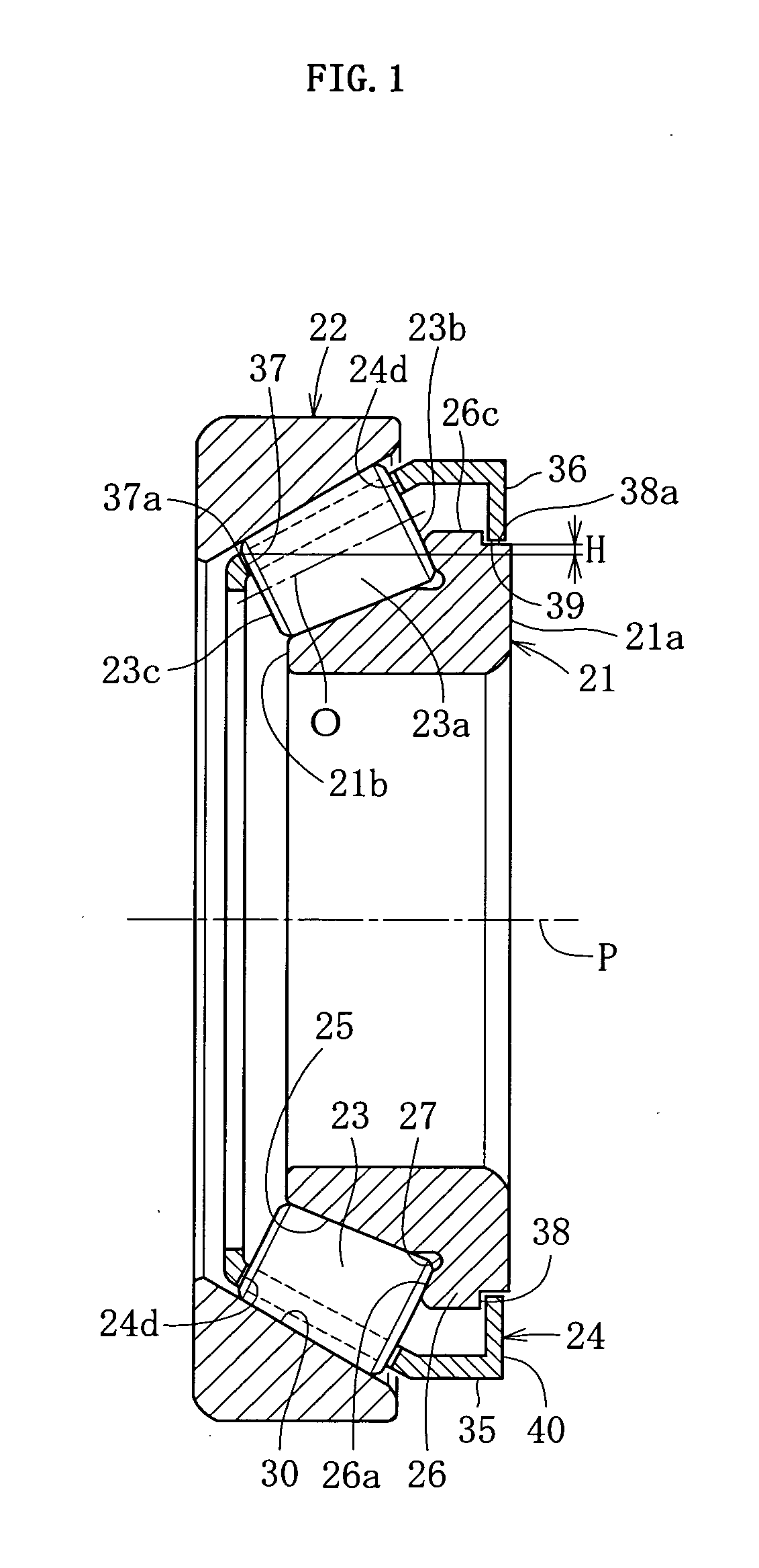
first embodiment

[0054]Therefore, the cage 24 does not project from the end face of the outer ring 22. Effects similar to those achieved by the tapered roller bearing can be achieved. In particular, because the small-diameter side end face 24f of the cage 24 does not project in the outward axial direction from the end face of the outer ring 22, when a double-row tapered roller bearing is configured, interference between the cages 24 can be prevented with certainty. Assembly is further enhanced.

[0055]In the explanation above, an example is given in which the tapered roller bearing is used in a power transmission system, such as a differential. However, the tapered roller bearing can be used for other purposes, such as for supporting a main shaft in a machine tool. Similar effects as those described above can also be achieved in this instance.

[0056]The embodiments of the present invention are described above. However, the present invention is not limited to the embodiments. Various modifications can ...


PUM


Abstract

The present invention provides a tapered roller bearing that can achieve improvement in manufacturability and a longer life. The tapered roller bearing of the present invention includes an outer ring 22, an inner ring 21, a plurality of tapered rollers 23 disposed between raceways of the inner ring and the outer ring, and a cage 24 that holds each tapered roller. A shoulder section 26 that receives a large end face 23b of the tapered roller 23 is provided on a large-diameter side of the inner ring 21 such as to project towards an outer-diameter side. A raceway 25 that reaches from the shoulder section 26 to the small diameter end is formed. An engaging section 36 that engages with the shoulder section 26 on the inner ring 21 is provided on a large-diameter side of the cage 24 such as to project towards an inner diameter direction. The engaging section 36 is disposed such as to fit within a width of a corresponding pocket 24d when viewed from an axial direction.

Description

TECHNICAL FIELD[0001]The present invention relates to a tapered roller bearing.BACKGROUND ART[0002]Driving force from an engine of an automobile is transmitted to the wheels through a power transmission system including any or all of a transmission, a propeller shaft, a differential, and a drive shaft.[0003]In the power transmission system, a tapered roller bearing having a high load-carrying capacity for radial load and excellent shock-resistant properties is often used as a bearing that supports a shaft. As shown in FIG. 6, the tapered roller bearing generally includes an inner ring 2, an outer ring 4, a plurality of tapered rollers 5, and a cage 6. The inner ring 2 has a conical raceway 1 on an outer circumferential side. The outer ring 4 has a conical raceway 3 on an inner circumferential side. The tapered rollers 5 are disposed between the inner ring 2 and the outer ring 4 such as to roll freely. The cage 6 holds the tapered rollers 5 at a predetermined interval in a circumfere...

Claims


Application Information

Patent Timeline
Patent Type & Authority Applications(United States)
IPC IPC(8): F16C33/58
CPCF16C19/364F16C33/543F16C33/4605
Inventor MATSUSHITA, TOMOKI
Owner NTN CORP
Why Eureka
Try Eureka