Fabricated Turbine Housing

a turbine and housing technology, applied in the direction of machines/engines, stators, liquid fuel engines, etc., can solve the problems of reducing the power affecting and the traditional turbine housing suffers from several deficiencies, so as to reduce the power of the turbine, and improve the efficiency of the turbocharger system

Inactive Publication Date: 2010-03-25
METALDYNE LLC
View PDF13 Cites 26 Cited by
  • Summary
  • Abstract
  • Description
  • Claims
  • Application Information

AI Technical Summary

Benefits of technology

[0005]Traditional turbine housings suffer from several deficiencies. For example, as explained in further detail below, cross-flow of exhaust within the volute housing can cause a decrease in turbine power. Additionally, the turbocharger system may experience power losses due to exhaust gas leaks at slip joints on the housing. Further, altering the size and geometry of the turbine to maximize output often requires replacing the housing and other housing components to fit the new turbine. Accordingly, there is a need in the art for an improved turbine housing.

Problems solved by technology

Traditional turbine housings suffer from several deficiencies.
For example, as explained in further detail below, cross-flow of exhaust within the volute housing can cause a decrease in turbine power.
Additionally, the turbocharger system may experience power losses due to exhaust gas leaks at slip joints on the housing.
Further, altering the size and geometry of the turbine to maximize output often requires replacing the housing and other housing components to fit the new turbine.

Method used


Image

  • Fabricated Turbine Housing
  • Fabricated Turbine Housing
  • Fabricated Turbine Housing

Examples


Embodiment Construction

[0023]Reference will now be made in detail to exemplary embodiments of the present invention, examples of which are illustrated in the accompanying drawings. It is to be understood that other embodiments may be utilized and structural and functional changes may be made without departing from the respective scope of the present invention.

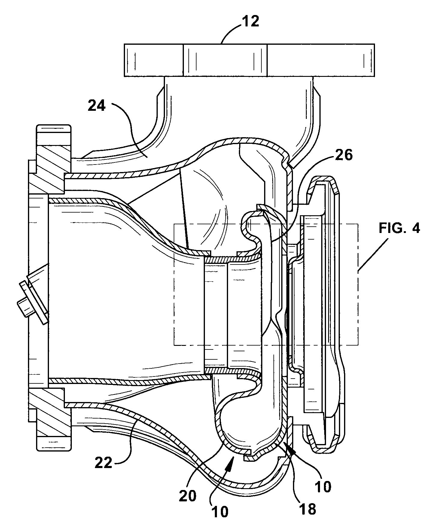
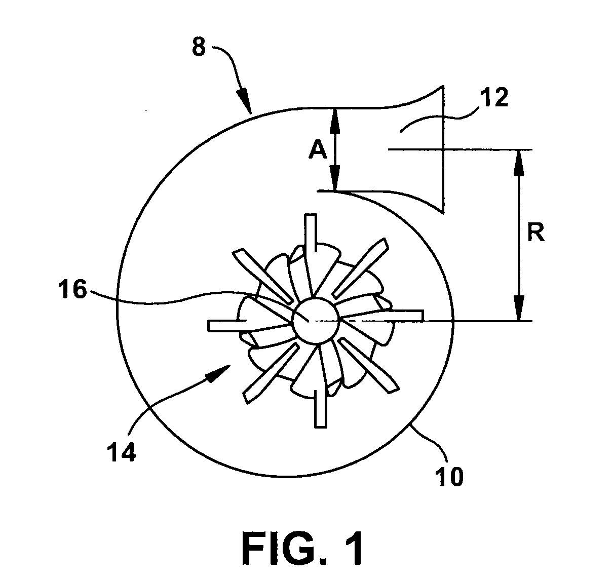
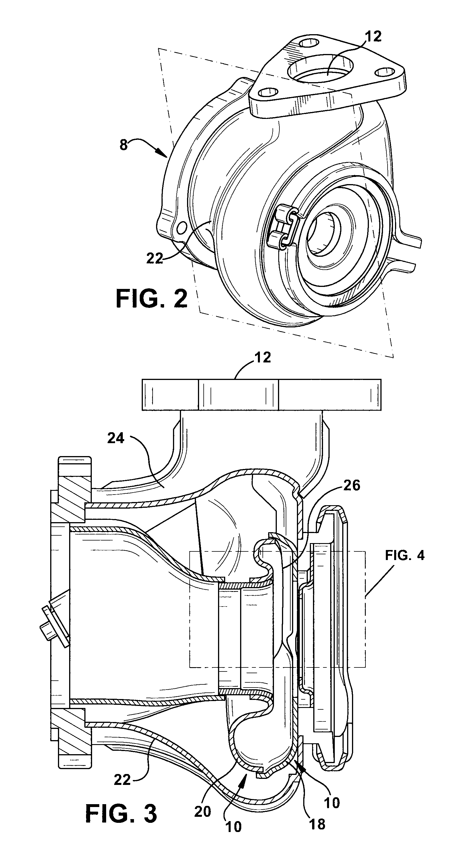
[0024]The efficiency of the power generated by a turbocharged engine may depend on the efficiency in which a turbine housing manages and channels the flow of the engine's exhaust through the turbine housing. FIG. 1 is a schematic illustration of a turbine housing 8. The turbine housing 8 includes a generally volute-shaped inner housing 10 and an inlet 12 at the opening of the inner housing 10. The volute shape and the position of the inlet 12 promote rotational flow within the inner housing 10. Such rotational flow spins a turbine 14 positioned generally in the center of the inner housing 10. As will be understood, as exhaust gases flow along the per...


PUM


Abstract

A turbine housing is provided. The turbine housing includes a tongue diverter to manage the interaction between exhaust gases entering the inlet of the housing and gasses flowing within the housing. The tongue member may also be arranged to produce a constant ratio throughout the turbine housing between the cross-sectional area of fluid passages and the distance between the centroid of that area and the axis of rotation of the turbine. The housing may comprise a pair of half shells that each form a portion of the tongue diverter.

Description

CROSS-REFERENCE TO RELATED APPLICATION[0001]This application claims benefit from U.S. Provisional Patent Application No. 61 / 192,758, entitled “Fabricated Turbine Housing Tongue Diverter,” filed on Sep. 22, 2008, U.S. Provisional Patent Application No. 61 / 192,759, entitled “Fabricated Turbine Housing Volute,” filed on Sep. 22, 2008, and U.S. Provisional Patent Application No. 61 / 206,559, entitled “Fabricated Turbine Housing,” filed on Jan. 30, 2009, which are hereby incorporated by reference in their entirety.FIELD OF INVENTION[0002]The present invention relates generally to turbine housings, and more particularly, to methods and apparatus for fabricating turbine housings.BACKGROUND[0003]As is known in the art, turbochargers are often used with combustion engines to increase the power output of the engine. Turbochargers increase power by increasing the amount of air used to facilitate combustion in the engine. Increasing the amount to air provided to the cylinders of the engine allow...

Claims


Application Information

Patent Timeline
Patent Type & Authority Applications(United States)
IPC IPC(8): F01D1/02
CPCF01D9/026F01D25/24F05D2230/80F05D2220/40F05D2230/52F02C6/12
Inventor PHILLIPS, JR., ROBERT ARTHURSCHMIDT, MICHAEL PAULBLACKIE, MICHAEL
Owner METALDYNE LLC
Why Eureka
Try Eureka