Differential vibration control for wind turbines

a technology of vibration sensing and control, applied in the field of wind turbines, can solve problems such as premature fatigue failure, unnecessary system shutdown, and reducing the life of components

Active Publication Date: 2010-03-25
GENERAL ELECTRIC WIND ENERGY +1
View PDF2 Cites 17 Cited by
  • Summary
  • Abstract
  • Description
  • Claims
  • Application Information

AI Technical Summary

Problems solved by technology

Vibrations in various components of a wind turbine may considerably reduce the life of those components and/or lead to early fatigue failures.
Howeve

Method used


Image

  • Differential vibration control for wind turbines
  • Differential vibration control for wind turbines
  • Differential vibration control for wind turbines

Examples


Embodiment Construction

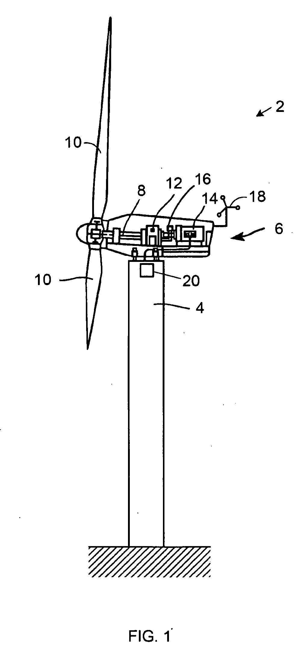
[0012]FIG. 1 illustrates one example of a wind turbine 2. This particular configuration for a wind generator type turbine includes a tower 4 supporting a nacelle 6 enclosing a drive train 8. The blades 10 are arranged on a hub to form a “rotor” at one end of the drive train 8 outside of the nacelle 6. The rotating blades 10 drive a gearbox 12 connected to an electrical generator 14 at the other end of the drive train 8 along with a control system 16 that may receive input from an anemometer 18. A first or tower vibration sensor 20 is arranged on the tower 4, such as near the top of the tower, or at any other location on the tower. Other vibration sensors may also be arranged at other locations on the tower 4 and / or at other locations on the wind turbine 2.

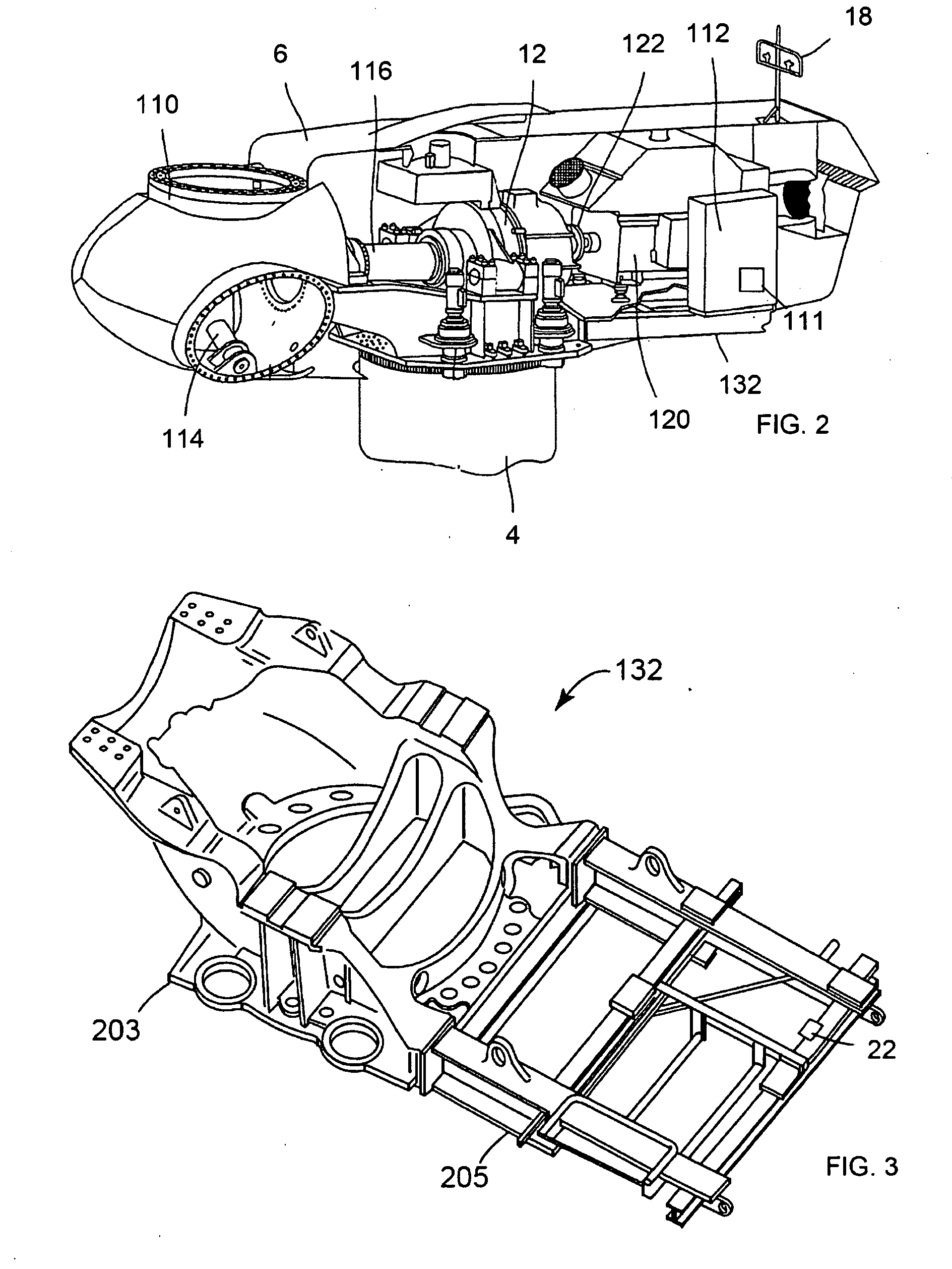
[0013]FIG. 2 is a cut-away orthographic view of the nacelle 6 and hub 110 of the wind turbine 2 shown in FIG. 1. The drive train 8 of the wind turbine 4 (shown in FIG. 1) includes a main rotor shaft 116 connected to hub 110 and the...


PUM


Abstract

A wind turbine includes a first vibration sensor for producing a first vibration signal; a second vibration sensor, displaced from the first vibration sensor, for producing a second vibration signal; and a processor for comparing the first vibration signal to the second vibration signal and controlling the wind turbine in response to the comparison.

Description

BACKGROUND OF THE INVENTION[0001]1. Technical Field[0002]The subject matter described here generally relates to wind turbines, and, more particularly, to differential vibration sensing and control of wind turbines.[0003]2. Related Art[0004]A wind turbine is a machine for converting the kinetic energy in wind into mechanical energy. If the mechanical energy is used directly by the machinery, such as to pump water or to grind wheat, then the wind turbine may be referred to as a windmill. Similarly, if the mechanical energy is converted to electricity, then the machine may also be referred to as a wind generator or wind power plant.[0005]Vibrations in various components of a wind turbine may considerably reduce the life of those components and / or lead to early fatigue failures. These vibrations are typically measured with respect to a stationary reference point using accelerometers arranged at critical locations on the components of interest. However, such conventional approaches to vi...

Claims


Application Information

Patent Timeline
IPC IPC(8): F03D7/00
CPCF03D7/0296F03D7/042Y02E10/723F05B2260/96F05B2270/334F05B2260/845Y02E10/72
Inventor GARRIDO, ALVARO CALLEYEGRO, EUGENIOCRESPO, MANUEL HUERTABENITO, PEDRO L.
Owner GENERAL ELECTRIC WIND ENERGY
Why Eureka
Try Eureka