Coat film forming method and coat film forming apparatus

a technology of forming method and forming apparatus, which is applied in the direction of membranes, vacuum evaporation coatings, coatings, etc., can solve the problems of difficult to secure a safety in the transfer task, and achieve the effect of shortening the operation time, easy execution and uniform thickness

Active Publication Date: 2010-03-25
NGK INSULATORS LTD
View PDF7 Cites 6 Cited by
  • Summary
  • Abstract
  • Description
  • Claims
  • Application Information

AI Technical Summary

Benefits of technology

[0018]According to the coating membrane forming method of the present invention, the operation to form a coating membrane on an object to be coated can be done by raising and lowering the liquid level of an application liquid without moving the object to be coated, and thus a large equipment to move the object to be coated is not necessary. In addition, there is no danger associated with a transfer task of a large object to be coated, and thus formation of a coating membrane can be done simply and safely. Further, if a lowering rate of the liquid level is made constant, a membrane with a uniform thickness may be formed independent of a weight or a shape of an object to be coated. In addition, if a plurality of objects to be coated are set in a dipping tank, coating films can be formed on a plurality of objects to be coated simultaneously, and thus an operation time for it can be shortened.
[0019]According to the coating membrane forming apparatus of the present invention, the coating membrane forming method of the present invention can be easily executed, and thus the effects resulting from the coating membrane forming method may be obtained. In addition, in the case that an object to be coated is in the shape of a tube or a monolith having an inner space communicating with outside, if a coating membrane is intended to be formed only on an inner surface surrounding the inner space, adhesion of an application liquid onto an outer peripheral face of the object to be coated can be avoided by providing a sealing member to seal between a top as well as a bottom of an outer peripheral face of the object to be coated and an inner face of a dipping tank without covering the entire outer peripheral face of the object to be coated with a sealing material, and thus the number of steps can be reduced. Further, in the case that the object to be coated is the one like a porous body, if a pressurized gas supply device for supplying a pressurized gas into a space formed by an inner peripheral face of the dipping tank, an outer peripheral face of the object to be coated, and the sealing members is provided, and the application liquid is sent while the pressurized gas is supplied into the space, the pressurized gas flows into pores of the porous body and thereby pressurizes inside pores, and this, in turn, suppresses penetration of the application liquid into the pores. With this, a coating membrane with more uniform thickness can be formed on the inner surface. Further, if the solution tank whose inner pressure can be controlled is used, a sending rate of the application liquid into the dipping tank can be increased by pressurizing inside the solution tank when the application liquid is sent into the tank. With this too, penetration of the application liquid into the pores can be suppressed.
[0020]In the case of using a pump to raise and lower the liquid level of the application liquid has a merit of making the equipment smaller, though there is a possibility that the lowering rate of the liquid level fluctuates more or less due to a pulsation of the pump. On the other hand, in the case of using the raising and lowering of the solution tank to raise and lower the liquid level of the application liquid has a merit of keeping the lowering rate of the liquid level constant easily and thereby forming a coating membrane with a uniform thickness easily, because there is no pulsation like using a pump, though the equipment becomes more or less larger as compared with the case of using a pump. In addition, a means without using a pump is advantageous in safety and durability when an application liquid of an organic solvent having a high solubility, volatility, and flammability, or a highly corrosive solution such as an acid and an alkali is used.

Problems solved by technology

However, when a volume or a weight of the object to be coated is large or heavy, the conventional applying method like this requires a large equipment for raising and lowering of the object to be coated associated with its immersion and pull-out, which also makes it difficult to secure a safety in transfer task.
Further, when a coating membrane is intended to be formed only on a part of a surface of the object to be coated, an entire part other than that part needs to be covered by a sealing material before the object to be coated is immersed in an application liquid, which is laborious.

Method used


Image

  • Coat film forming method and coat film forming apparatus
  • Coat film forming method and coat film forming apparatus
  • Coat film forming method and coat film forming apparatus

Examples


example 1

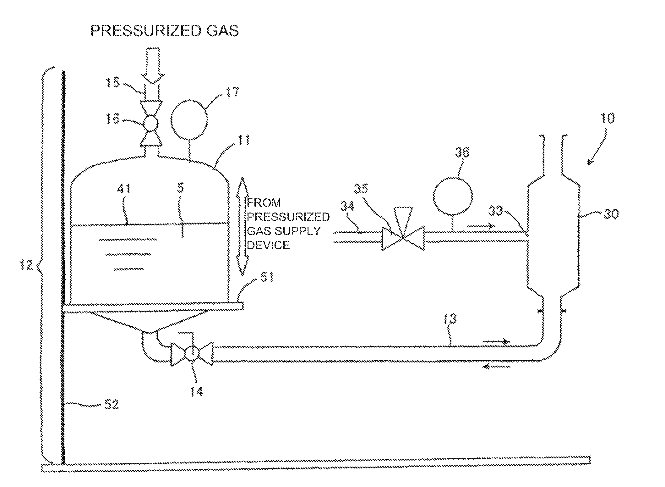
[0056]A porous body with a monolith form having a plurality of cells and with a column-shaped appearance (diameter of 180 mm and length of 1,000 mm, with glass-sealed end faces) was used as the object to be coated. The object to be coated 1 was set in the dipping tank 30 of the coating membrane forming apparatus 10 as shown in FIG. 1 with the sealing members (packing) 31 set as shown in FIG. 3 so that a coating membrane comprising a thermosetting polyimide resin precursor would be formed on the inner peripheral face of the cells. A solution of the thermosetting polyimide resin precursor was filled in the solution tank 11 with the valve 14 being closed. Then, the solution tank 11 was raised until its liquid level reached above the top end of the object to be coated 1 while supplying a pressurized gas into the solution tank 11 to pressurize inside of the solution tank 11.

[0057]Thereafter, the solution in the solution tank 11 was sent into the dipping tank 30 by opening the valve 14 wh...

example 2

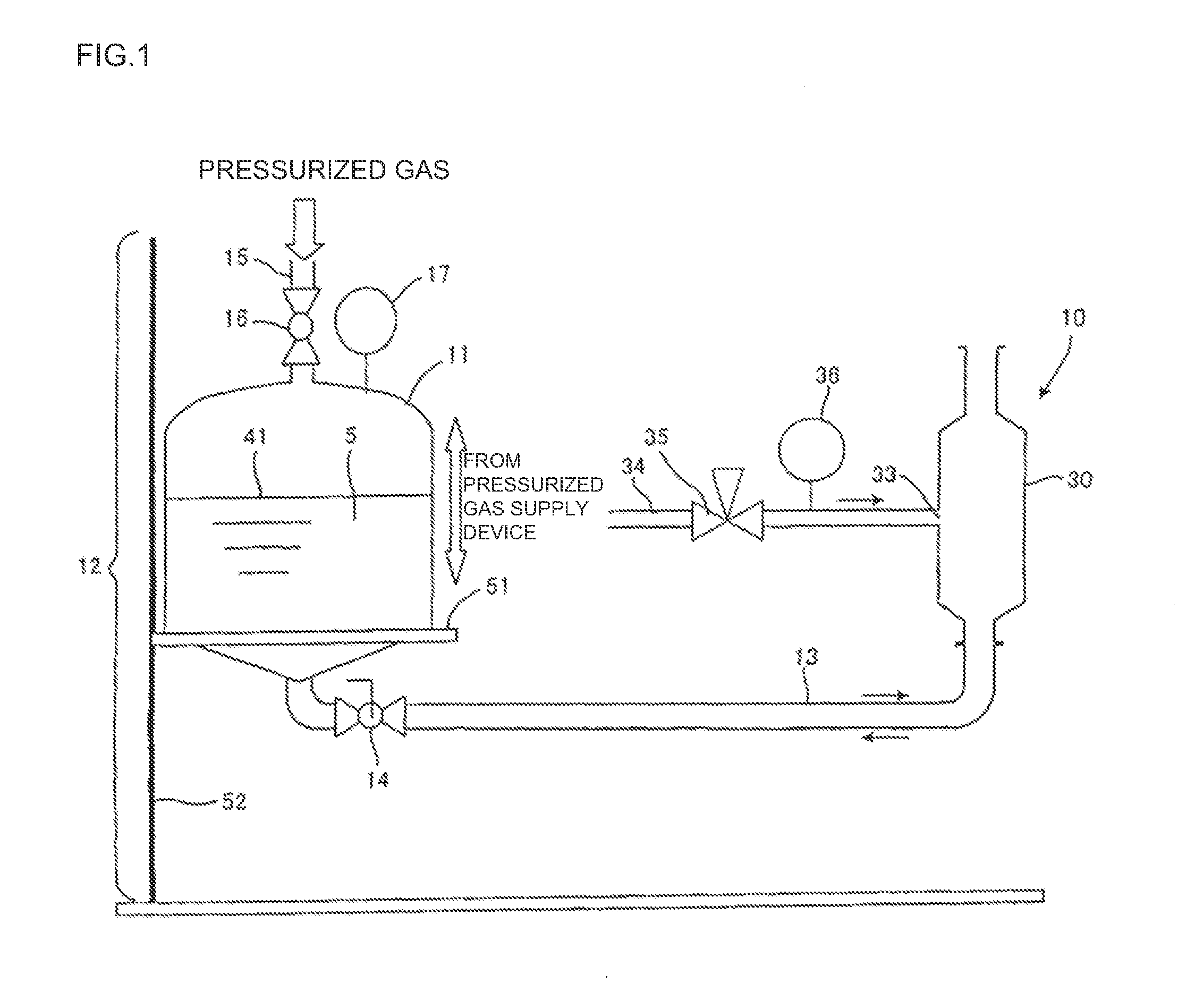
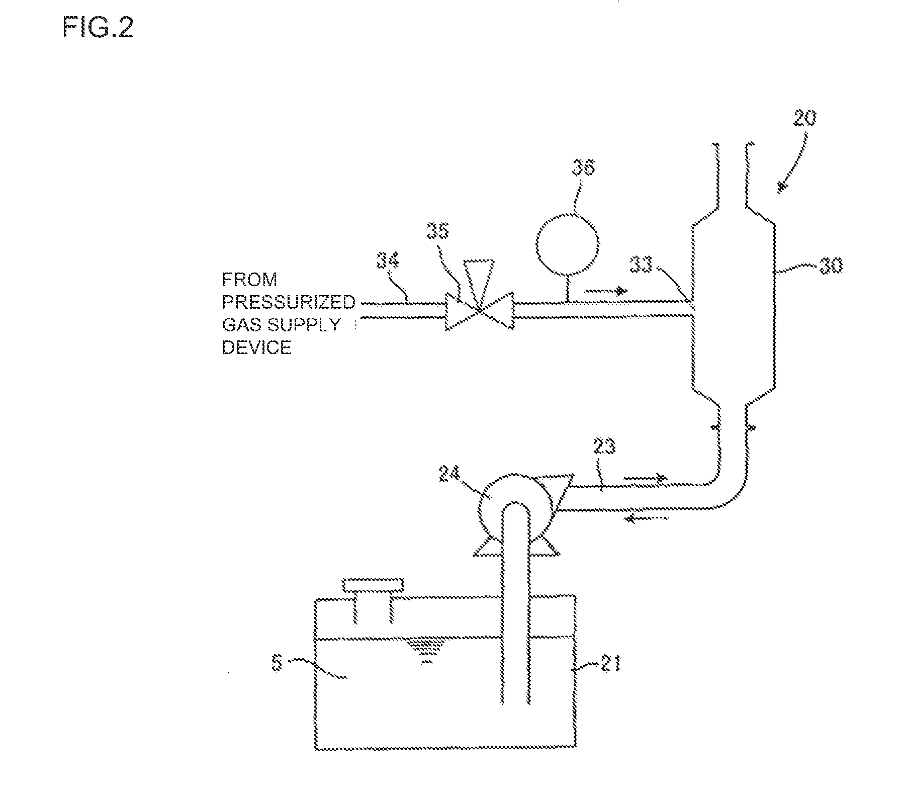
[0059]A porous body with a monolith form having a plurality of cells and with a column-shaped appearance (diameter of 180 mm and length of 1,000 mm, with glass-sealed end faces) was used as the object to be coated. The object to be coated 1 was set in the dipping tank 30 of the coating membrane forming apparatus 20 as shown in FIG. 2 with the sealing materials (packing) 31 set as shown in FIG. 3 so that a coating membrane comprising a thermosetting polyimide resin precursor would be formed on the inner peripheral face of the cells.

[0060]Thereafter, as shown in FIG. 3, the thermosetting polyimide resin precursor solution filled in the solution tank 21 was sent into the dipping tank 30 by rotating the pump 24 (forward rotation) while supplying a pressurized gas into the space 32 formed by the inner peripheral face of the dipping tank 30, the outer peripheral face of the object to be coated 1, and the sealing members (packing) 31. The solution sent into the dipping tank 30 in the way a...

example 3

[0062]Fifteen porous bodies with tube forms (outer diameter of 10 mm and length of 1,000 mm) were used as the objects to be coated. These 15 tubular objects to be coated were set in the dipping tank 30 of the coating membrane forming apparatus 10 as shown in FIG. 1 with their opened area at the both ends being plugged with a masking material so that a coating membrane comprising a thermosetting polyimide resin precursor would be formed on their outer peripheral faces simultaneously. A solution of the thermosetting polyimide resin precursor was filled in the solution tank 11 with the valve 14 being closed. Then, the solution tank 11 was raised until its liquid level reached above the top end of the object to be coated while supplying a pressurized gas into the solution tank 11 to pressurize inside the solution tank 11.

[0063]Then, the valve 14 was opened to send the solution in the solution tank 11 into the dipping tank 30. The solution sent into the dipping tank 30 in the way as ment...


PUM

PropertyMeasurementUnit
contact timeaaaaaaaaaa
pressure gaugeaaaaaaaaaa
pressureaaaaaaaaaa

Abstract

A coating membrane forming method for forming a coating membrane on an object to be coated, the method comprising the steps of: setting the object to be coated for forming a coating membrane thereon in a dipping tank; sending an application liquid for forming the coating membrane into the dipping tank to raise a liquid level of the application liquid till the top of a region for forming the coating membrane thereon in the object to be coated is immersed in the application liquid; and thereafter discharging the application liquid outside the dipping tank to lower the liquid level of the application liquid.

Description

TECHNICAL FIELD[0001]The present invention relates to a method and an apparatus for forming a coating membrane having various functions on a surface of an object.BACKGROUND ART[0002]As a filter to separate a specific gas or liquid from a mixture of a plurality of kinds of gases or liquids, a porous body having a separation membrane formed on its surface is known. Formation of this separation membrane is made by applying a solution containing a precursor to the separation membrane onto a surface of a porous body for forming the separation membrane thereon, thus forming a coating membrane (membrane formation), and followed by performing drying and heat-treatment on thus obtained coating membrane.[0003]Manufacturing a printed wiring circuit board includes the step of forming a resist film having a uniform thickness on a surface of the board, which is done by applying a resist solution onto the surface of the board.[0004]As a method of applying a liquid for forming a membrane (applicati...

Claims


Application Information

Patent Timeline
Patent Type & Authority Applications(United States)
IPC IPC(8): B05D1/18B05C3/00
CPCB01D63/066B01D2323/42B01D71/021B01D67/0088
Inventor NONOKAWA, MASAMIICHIKAWA, AKIMASA
Owner NGK INSULATORS LTD
Why Eureka
Try Eureka