Solid-state structure comprising a battery and a variable capacitor having a capacitance which is controlled by the state-of-charge of the battery

Inactive Publication Date: 2010-03-25
KONINKLIJKE PHILIPS ELECTRONICS NV
View PDF2 Cites 11 Cited by
  • Summary
  • Abstract
  • Description
  • Claims
  • Application Information

AI Technical Summary

Benefits of technology

[0034]The invention also provides an electrical device comprising an electrochemical energy source as claimed in any of the preceding claims. Also in such an embodiment the fruitful effects of the invention appear very well.
[0035]Yet another embodiment provides the feature that the second capacitor plate is provided by flip-chipping a second substrate with a fixed capacitor plate on the assembly, leading to a particular attractive method for producing a capacitor according to the present invention.

Problems solved by technology

However when one of these effects is substantially stronger than the other a contraction or expansion of the battery stack as a whole results.

Method used


Image

  • Solid-state structure comprising a battery and a variable capacitor having a capacitance which is controlled by the state-of-charge of the battery
  • Solid-state structure comprising a battery and a variable capacitor having a capacitance which is controlled by the state-of-charge of the battery
  • Solid-state structure comprising a battery and a variable capacitor having a capacitance which is controlled by the state-of-charge of the battery

Examples


Embodiment Construction

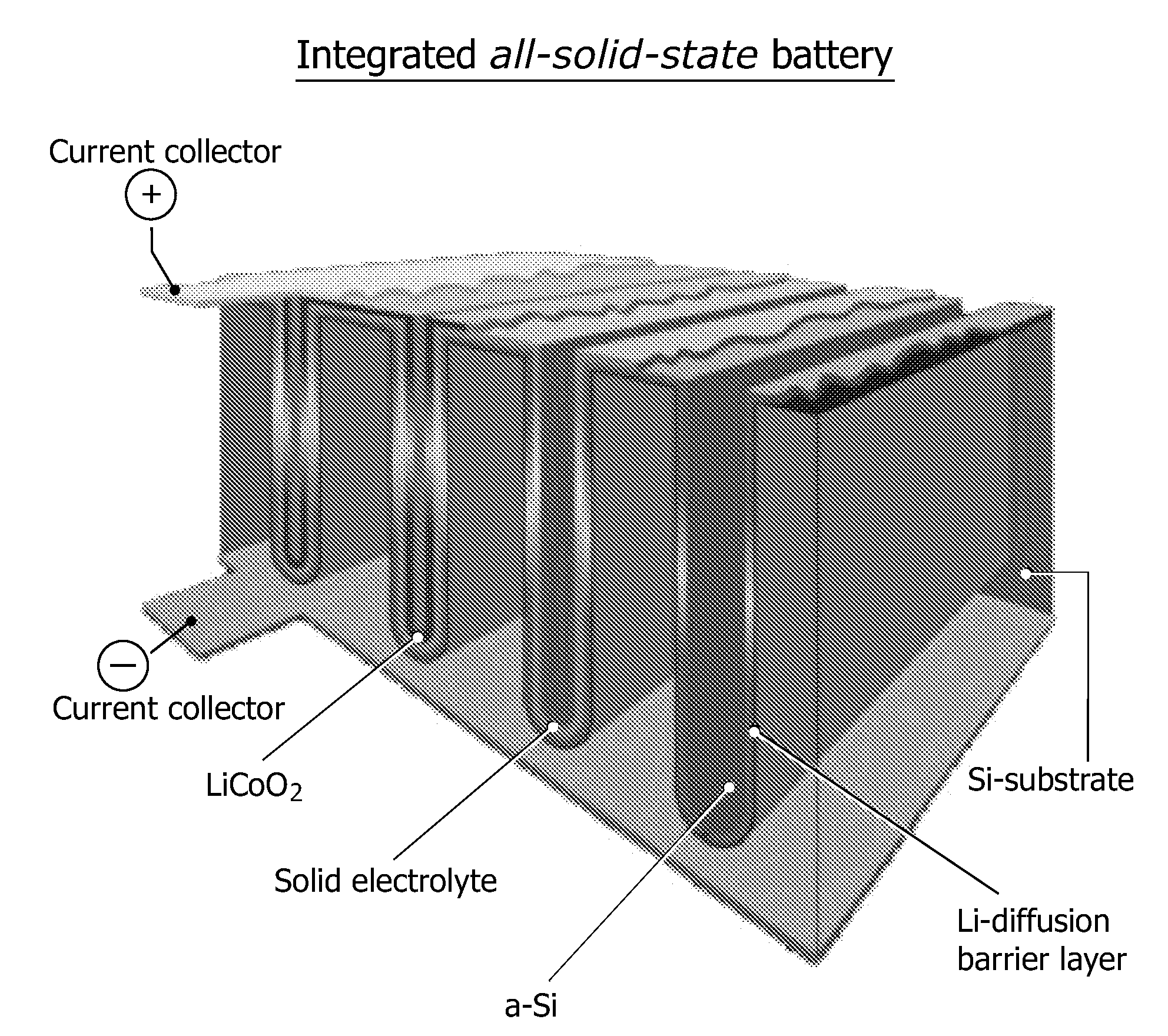
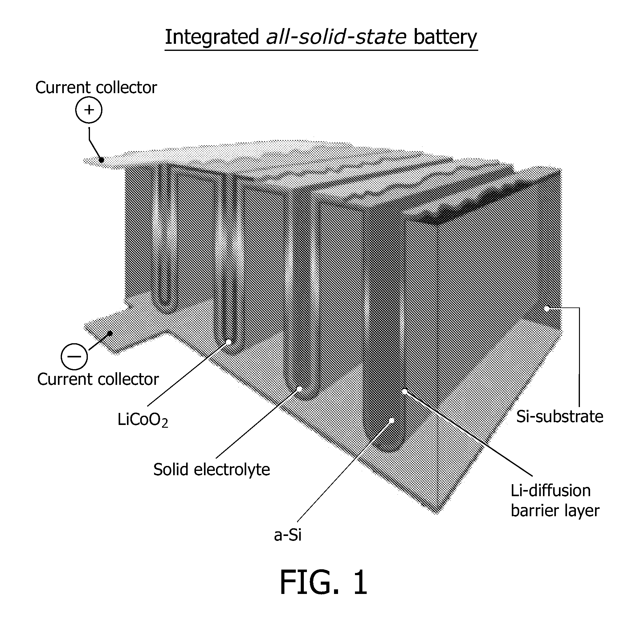
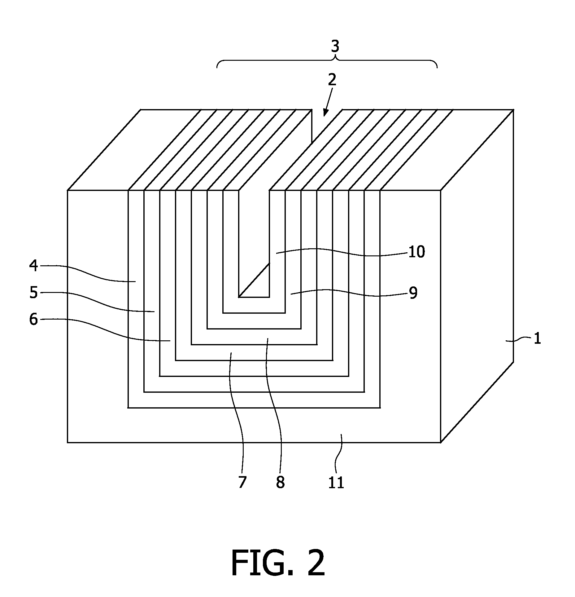
[0042]FIG. 1 shows the all solid-state thin film battery disclosed in document WO2005 / 027245A2. Using the deposition and integration technology described in this prior art document, a stack can be manufactured that can be used to make an electrochemically tunable capacitor. This stack is depicted in FIG. 2. In this figure a schematic representation is shown of a single trench in a substrate 1 in which a trench 2 is formed wherein a battery stack denoted in its whole by 3 is deposited according to the prior art method mentioned above.

[0043]This battery stack 3 applied on the substrate 1 comprises a current collector layer 4, a cathode layer 5, an solid-state electrolyte layer 6 and an anode layer 7. On top of the anode layer 7 a current collector layer 8 is deposited. On the thus formed battery stack 3 a dielectric layer 9 is deposited and thereon conductive layer 10, which will be used as the capacitor plate from the current collector layer 8. The dielectric layer 9 shields and insu...


PUM

PropertyMeasurementUnit
DC voltageaaaaaaaaaa
voltageaaaaaaaaaa
voltageaaaaaaaaaa

Abstract

The present invention relates to a solid-state variable capacitor, comprising a first capacitor plate (10), a second capacitor plate (12), extending substantially parallel to the first capacitor plate (10) and on a distance from said first capacitor plate, wherein at least the first capacitor plate (10) is structurally coupled to one side of a first layered solid-state battery wherein the layers (4-8) of said first solid-state battery (3) extend substantially parallel to the first capacitor plate (10) and wherein the first solid-state battery is susceptible to variations in the size in the direction perpendicular to the plane of its layers (4-8). This invention is based on the realization that the thickness of a solid-state battery (3) varies with conditions prevailing in the battery. The movable capacitor plate (10) causes a change of the capacitance value of the capacitor.

Description

FIELD OF THE INVENTION[0001]Presently, many variations of possible integrated capacitors are utilized in IC design. However, depending on the electrical circuit it is often desirable that at least some of these capacitors are not of constant value, but are variable or tunable. Currently, controllable capacitors based on MEMS technology exist. These are the microscopic equivalent of air-spaced variable capacitors and can be integrated into silicon chips using conventional wafer fabrication processes. In these devices the capacitance value can be tuned in a continuous manner by applying, for example, a DC voltage across a beam / membrane structure.BACKGROUND OF THE INVENTION[0002]Although controllable or tunable MEMS capacitors are widely investigated, these devices employ freestanding beams or membranes that are prone to collapse or get stuck in a “closed” state. This can result from poor processing during the under-etching of the beams or after the application of too high a DC voltage...

Claims


Application Information

Patent Timeline
Patent Type & Authority Applications(United States)
IPC IPC(8): H01M12/00
CPCH01G5/011H01M12/005H01M10/0436H01M10/00Y02E60/10
Inventor NIESSEN, ROGIER ADRIANUS HENRICANOTTEN, PETRUS HENRICUS LAURENTIUSOP HET VELD, JOHANNES HUBERTUS GERARDUSPIJNENBURG, REMCO HENRICUS WILHELMUS
Owner KONINKLIJKE PHILIPS ELECTRONICS NV
Why Eureka
Try Eureka